Order No.
35 MHz: F 8042
40 MHz: F 8043
41 MHz: F 8044
FX-30
15.6 THROTTLE / MOTOR MIXER
This function is used to program a mixer which affects the
position of the throttle servo when a ‘pitch-axis’ (elevator),
‘roll-axis’ (aileron) or ‘tail rotor’ command is applied at the
transmitter. The settings are adjusted separately. Once set up
correctly, this mixer ensures that motor speed is not affected
when you operate any of the three functions mentioned above.
I
n addition to the mixer it is possible to program an accelera-
tion function for the throttle servo to obtain the optimum cor-
rective setting.
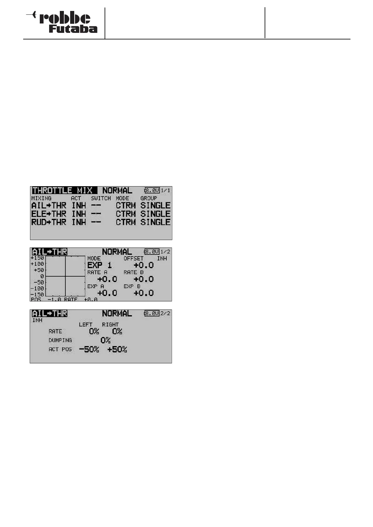
Use the 3-D hot-key to mark the ‘THROTTLE MIX’ option in
the Helicopter Model menu, and confirm your choice with
EDIT. The screen display has one level (page), but two sub-
menus are present for each mixer: in each case a separate
graphic display for programming the mixer curve, and one for
s
etting the acceleration function. The two lower screen shots
are typical displays for the ‘Roll -> throttle’ mixer.
The first step is to move to the second column and follow the
standard procedure to activate each mixer which is to be
used: mark the field, enter the setting using the ‘3-D hot-key’,
and conclude the activation with EDIT. The field now displays
‘ON’ or ‘OFF’, according to the position of the switch.
The effects and method of setting the ‘Global’ or ‘Separate’
mode have already been described; the function is pro-
grammed using the ‘Mode’ column. Define a switch and its
direction of operation in the usual way, using the ‘SWITCH’
column. The default setting is ‘--’, i.e. the mixer is permanent-
ly switched on.
The mixer function itself is actually set up in the sub-menu,
with the help of the associated curve: mark the appropriate
line in the ‘MIXER’ column, confirm with EDIT, and the curve
display appears. The curve can then be programmed using the
f
amiliar procedure: first select the curve type: mark the
‘MODE’ field in the topmost display, and select the settings
using the ‘3-D hot-key’. The method of programming a mixer
curve is exactly as described in Section 15.2 on page 63; ple-
ase refer back to that section if you are not sure.
The acceleration function is set up on the third menu page;
please refer to Section 15.3 on page 64 for details. For each
mixer a percentage value (Rate) can be entered separately for
b
oth maximum travels of the stick (Left and Right): mark the
field, enter the setting using the ‘3-D hot-key’, and conclude
the programming with EDIT. The setting is displayed in the
field as a % value. You can also enter a percentage value
(actually a time period) in the ‘Damping’ field; this determines
how long the function is to remain active once the change in
setting has been carried out.
In the bottom line - ‘ACT-POS’ - you can define a point for
both sides which represents the position from which the func-
tion is to take effect: mark the appropriate field, enter the set-
ting using the ‘3-D hot-key’, then conclude the procedure with
EDIT. The default settings are 50% for left, and +50% for right.
Holding the ‘EDIT’ button pressed in for at least one second
restores the defaults.
67