Order No.
35 MHz: F 8042
40 MHz: F 8043
41 MHz: F 8044
FX-30
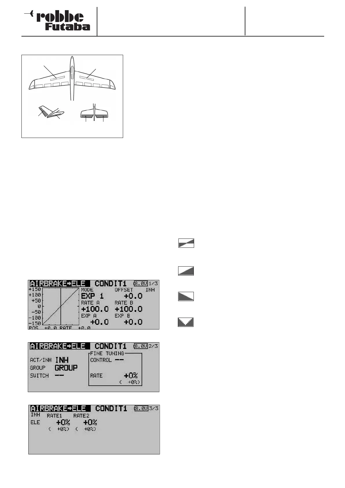
14.6 AIRBRAKE -> ELEVATOR MIXER
This menu is
used to set up a
mixer which
causes the ele-
vator to deflect
when the airbra-
k
es are exten-
ded.
When airbrakes
are deployed, a
pitch trim chan-
ge often occurs
- this applies to
many models. Without a suitable mixer, the pilot then has to
c
ompensate for this by applying down-elevator manually. The
FX-30 includes a mixer which carries out this pitch trim corre-
ction automatically.
The exact mixer values for the elevator servo(s) can be adjus-
ted separately. The function can be activated using a switch
which is user-selectable. As with many functions, it is also
possible to determine whether the settings are to apply to all
flight modes (Global) or only to the currently activated flight
mode (Separate). It is possible to assign an auxiliary control for
fine-tuning the function.
This mixer is only available if you have already programmed a
wing type which features airbrakes; this is carried out in the
Model Type Select section of the Base menu.
Use the 3-D hot-key to mark the ‘Airbrake -> elevator’ mixer in
the Model menu, and confirm your choice with EDIT. The menu
has three levels (pages), which look like this:
As ever, this mixer function must first be activated in the ‘ACT
/ INA’ line: first mark the field, enter the setting using the ‘3-D
hot-key’, and conclude the activation with EDIT. The screen
will now display ‘On’ or ‘OFF’, according to the current posi-
tion of the switch.
T
he effects and method of setting the ‘Global’ or ‘Separate’
mode have already been described; the function is pro-
grammed in the ‘Mode’ line. In the ‘Switch’ line a switch can
be selected in the familiar manner, and its direction of opera-
tion determined. The default setting here is ‘NONE’, i.e. the
mixer is always switched on.
On the second page of the menu the fine-tuning settings can
be carried out in the separate frame marked ‘Fine Trim’. It is
p
ossible to assign a transmitter control to the task of fine-
tuning the mixer setting. First select the transmitter control you
wish to use for this purpose; this is accomplished in the
‘Transmitter control’ field: mark the corresponding field and
use the ‘3-D hot-key’ to make your selection in the Switch /
Transmitter Control Select menu. Any of the auxiliary transmit-
ter controls can be selected for the task.
The next step is to define the operating mode for the trans-
mitter control you have chosen; this is carried out using the
now familiar procedure: use the 3-D hot-key to mark the
‘Mode’ field, then make your selection. Four modes are avai-
lable in total, and their method of working is displayed on-
screen in schematic form. This is the key to the symbols:
The mixer rate is 0% when the transmitter control
is in the centre position. Moving the transmitter
control to right or left increases and reduces the
value respectively.
The mixer rate is 0% at the left end-point of the
transmitter control. Moving the transmitter control
to the right increases the value.
The mixer rate is 0% at the right end-point of the
transmitter control. Moving the transmitter control
to the left increases the value.
The mixer rate is 0% when the transmitter control
is in the centre position. Moving the transmitter
control to right or left always increases the value.
A mixer curve can be programmed using the by now familiar
method, separately for each side of travel. The actual mixer
rates for the elevators are entered on the third page of the
menu: for each control surface the mixer rate can be entered
as a % value. The method is exactly the same as previously
described.
51
Left airbrake
Right airbrake
V
-tail Ailvator
ELEVATOR
E
LE
RUDDER
ELE2