O
rder No.
35 MHz: F 8042
40 MHz: F 8043
41 MHz: F 8044
FX-30
13
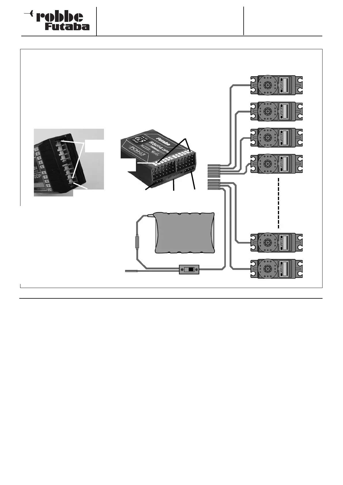
5.1 CONNECTING SERVOS - PCM 1024 AND PCM 2048 (G3)
Charge socket On / Off switch
Receiver battery
Servos
1 … 10 / 12
10/B = battery,
or channel 10
Channels
1
… 9
Connecting servos and power supply:
R 1410 DP receiver
S
ocket: 10/B = receiver battery or servo for 10th channel, using Y-lead if necessary
Outputs 1 … 9: 1 … 9 proportional channels for servos
Note:
If the number of powerful analogue or
digital servos connected to the recei-
ver is high, the standard switch har-
ness supplied in the set will not be
capable of handling the heavy cur-
rents which will flow. In such systems
it is necessary to use a suitable high-
current power supply (usually known
as a Power battery backer) to supply
the servos and receiver. Ask at a spe-
cialist model shop for details.
NEW SYSTEM FOR FUNCTION SEQUENCE
For the PCM-G3 system the second aileron output has been
shifted to output 5, in order to maintain compatibility with
small five-channel and six-channel receivers; the increased
number of channels has also necessitated this change. This
means that the receiver channel sequence is not the same as
that of the PCM 1024 system.
To maintain compatibility with the PCM-1024 system it is pos-
sible to select any function sequence you like; this is accom-
plished in the “Function” menu.
Note:
If you need to change the function sequence when using the
PCM-G3 system, please ensure that associated functions are
allocated together within the channel groups 1 … 6 or 7 … 12.
Do not assign paired functions to channels 6 and 7, as this
could result in different servo transit times.
The transmitter employs a new, graphical method of selecting
the model type as basis for the mixer functions and transmit-
ter control arrangement (stick mode), and this automatically
generates a suggested configuration for the selected model
type. We recommend that you keep to this set-up if possible,
so that you are always using a standard configuration.
The “Function” menu clearly shows the output to which the
corresponding servo is connected, and which transmitter con-
trol is used to operate it. Where a single function operates two
or more servos, the corresponding transmitter controls are
configured accordingly.
Within an individual model type the configuration varies little,
although the number of channels in use may increase if the
number of wing flaps and other control surfaces is higher than
usual.
The situation is different when you switch from one model type
to another. For example, if you change the model type from a
normal tail to a tail layout with two elevator servos (Ailvator),
the sequence of functions is necessarily different.
The same also applies, of course, to model gliders (powered
and unpowered), and for flying wing models with and without
winglets.
The following pages contain comprehensive tables and sket-
ches which clearly show the servo connection sequence,
arranged according to the different model types which are
managed by the software.
R 5114 DPS receiver
Socket: B/C = receiver battery or DSC lead
Outputs 1 … 12: 1 … 12 proportional channels for servos
Outputs DG1 and DG2: Switched channels 13 and 14
Monitor LED: Indicates the status of the wireless spot frequency transmission
Channels
1 … 12
Channel
DG2 = 14
Channel
DG1 = 13
Monitor
LED
Battery /
DSC