Order No.
35 MHz: F 8042
40 MHz: F 8043
41 MHz: F 8044
FX-30
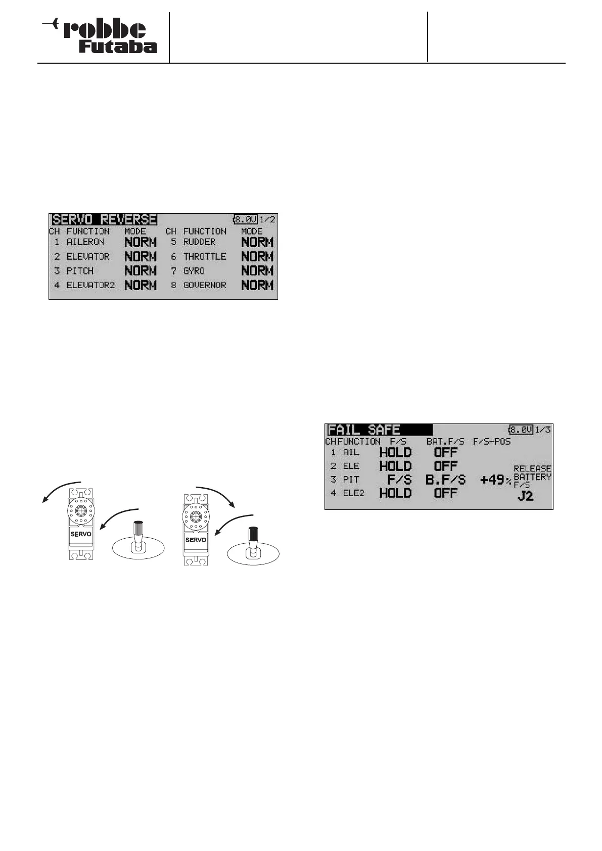
12.7 SERVO REVERSE
This function is used to reverse the direction of servo rotation
electronically; it is available separately for all servos. This
means that you do not have to consider the direction of rota-
tion when installing the servos in a model. It is important to set
the correct direction of servo rotation using this function
before you start programming additional model data.
Use the 3-D hot-key to mark the ‘Servo reverse’ option in the
Base menu, and confirm your choice with EDIT.
This menu has a second level (page) for channels 9 to 12; the
page number on the right-hand side indicates this. The dire-
ction of rotation of the servos is shown in each display field as
either ‘NORMAL’ or ‘REVERSE’.
To change a setting you must first use the cursor to mark the
appropriate channel. Once you have selected the correct
channel, you can change the direction of servo rotation from
‘NORMAL’ to ‘REVERSE’ or vice versa by turning the 3-D hot-
key. Pressing the ‘EDIT’ button concludes the servo reverse
procedure.
This drawing shows the normal and reversed directions of
rotation of one servo.
12.8 FAIL-SAFE SETTINGS
This function is only available in PCM-G3 and PCM-1024
mode. This means that the corresponding modulation process
must be set at the transmitter, and a matching PCM receiver
must be installed in the model.
In the Fail-Safe menu you can set the following parameters for
channels 1 … 8:
1. ‘HOLD’ mode: the last fault-free signals are stored tempo-
rarily in the receiver, and are passed on to the servos if inter-
ference should occur. These servo positions are maintained
(‘held’) until such time as valid signals are picked up from the
transmitter again. This is the default mode.
2. (F/S) Fail-Safe position: when interference strikes, the ser-
vos run to pre-programmed positions which are set at the
transmitter; these settings are also stored temporarily in the
receiver.
3. An additional feature - the ‘Battery Fail-Safe’ function: as
soon as the voltage of the receiver battery falls below a value
of about 3.8 V, the servos for which B/FS has been selected
run to pre-selected positions in order to warn the pilot that the
airborne battery is almost flat. If this should happen, you
must land immediately.
Recommended setting: for power models set the motor to
the idle position and a gentle turn; for gliders: flaps to launch
position or airbrakes extended.
Helicopter mode: throttle to around 80%.
Use the 3-D hot-key to mark the ‘FAIL-SAFE’ option in the
Base menu, and confirm your choice with EDIT.
This menu has a second level (page) for channels 5 to 12; the
page number on the right-hand side indicates this. Use the 3-
D hot-key to mark the ‘F/S’ field of the channel for which the
Fail-Safe settings are to be altered. Turn the ‘3-D hot-key’ to
the left to change the mode from ‘HOLD’ to ‘F/S’. You must
press the ‘EDIT’ button to confirm your choice.
If you opt for ‘Fail-Safe’, it is then necessary to enter the cor-
rect settings for the servo positions. This is carried out by
using the 3-D hot-key to mark the F/S-POS field at the far right
end of the corresponding channel. Now move the associated
transmitter control to the desired position, and press the
‘EDIT’ button. The servo position you enter is now displayed
as a percentage figure. This process has to be repeated for all
the channels which you have set to ‘F/S’ mode.
To change the setting from ‘F/S’ back to ‘HOLD’, mark the left-
hand field of the corresponding channel before turning the ‘3-
D hot-key’ to the right; press the ‘EDIT’ button to confirm.
33