Order No.
35 MHz: F 8042
40 MHz: F 8043
41 MHz: F 8044
FX-30
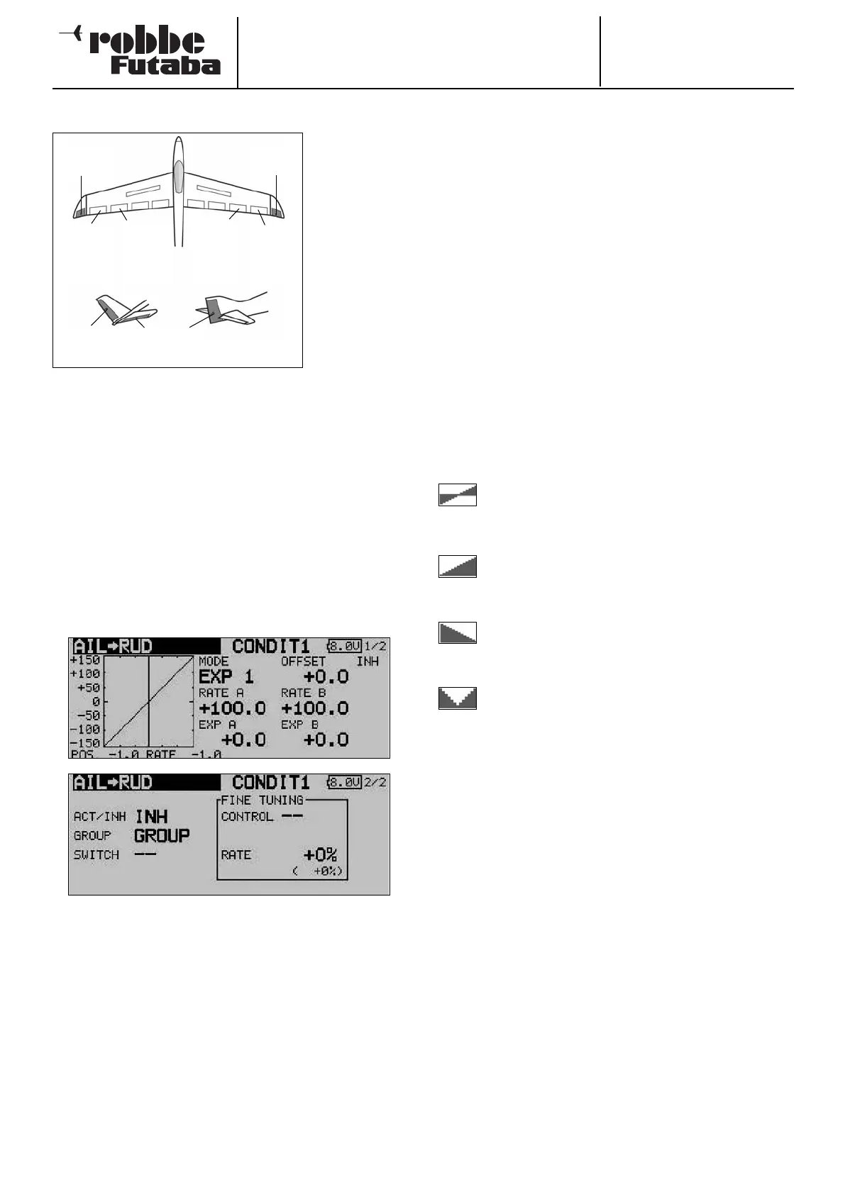
14.5 AILERON -> RUDDER MIXER
This menu is
used for setting
up a mixer
which causes
the rudder (and
the winglet rud-
d
ers, if present)
to move in the
same direction
when an aileron
command is
given.
When this func-
tion is activated,
t
he ailerons and
rudder(s) are coupled, so that only one stick has to be opera-
ted in order to turn the model effectively. This function is parti-
cularly useful for controlling large-scale model aeroplanes, as
it eliminates adverse yaw completely when set up correctly.
It is possible to set up a curve in order to obtain the exact
mixer rates required for a particular model. The function can
be activated using a switch which you can select. As with
many functions, it is also possible to determine whether the
settings are to apply to all flight modes (Global) or only to the
currently activated flight mode (Separate). An auxiliary trans-
mitter control can be assigned to the function for fine-tuning.
Use the 3-D hot-key to mark the ‘Aileron -> rudder’ mixer in
the Model menu, and confirm your choice with EDIT. The menu
has two levels (pages), which look like this:
The function must first be activated in the ‘ACT / INA’ line, as
previously described: first mark the field, enter the settings
using the ‘3-D hot-key’, and conclude the activation with EDIT.
You will now see ‘ON’ or ‘OFF’ in the field, according to the
position of the switch.
The effects and settings for the programming of ‘Global’ or
‘Separate’ mode have already been described repeatedly;
they are altered in the ‘Mode’ line. In the ‘Switch’ line a switch
can be selected in the familiar manner, and its direction of ope-
ration determined. The default setting here is ‘NONE’, i.e. the
mixer is always switched on.
A mixer curve can be set up and programmed on the first page
of the menu using the usual procedure.
This mixer curve determines the rate of following, i.e. the
extent to which the rudder moves (in the same direction) when
an aileron command is given.
On the second page of the menu the fine-tuning settings can
be carried out in the separate frame marked ‘Fine Trim’. It is
possible to assign a transmitter control to the task of fine-
tuning the mixer setting. First select the transmitter control you
wish to use for this purpose; this is carried out in the ‘Trans-
mitter control’ field: mark the corresponding field and use the
‘3-D hot-key’ to make your selection in the Switch / Transmit-
ter Control Select menu. Any of the auxiliary transmitter con-
t
rols can be selected for this purpose.
The next step is to define the operating mode for the transmit-
ter control you have chosen; this is carried out using the now
familiar procedure: use the 3-D hot-key to mark the ‘Mode’
field, then make your selection. Four modes are available in
total, and their method of working is displayed in schematic
form on the screen. This is the key to the symbols:
The mixer rate is 0% when the transmitter control
is in the centre position. Moving the transmitter
control to right or left increases and reduces the
value respectively.
The mixer rate is 0% at the left end-point of the
transmitter control. Moving the transmitter control
to the right increases the value.
The mixer rate is 0% at the right end-point of the
transmitter control. Moving the transmitter control
to the left increases the value.
The mixer rate is 0% when the transmitter control
is in the centre position. Moving the transmitter
control to right or left always increases the value.
50
Main
aileron
(
AIL2)
Chip
aileron
(AIL4)
Chip
aileron
(AIL3)
Main
aileron
(AIL)
ELEVATOR
V-tail Normal tail
RUDDER
Winglet
(RUD)
Winglet
(RUD2)