Order No.
3
5 MHz: F 8042
40 MHz: F 8043
41 MHz: F 8044
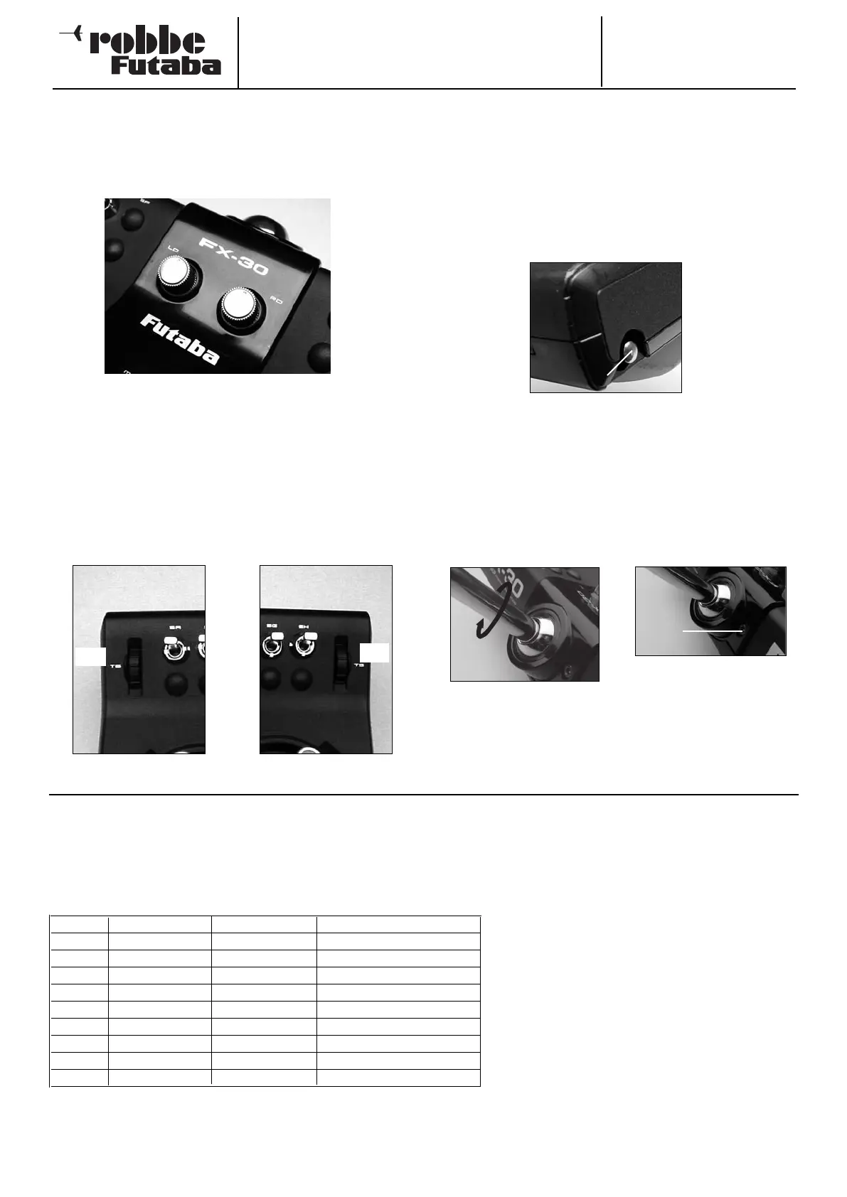
FX-30
4.12 ROTARY KNOBS
The rotary knobs LD and RD are analogue controls which can
be assigned freely to any function. They feature a fine centre
detent, and the transmitter emits an audible signal when they
are moved to the centre position.
The markers indicate the set position.
4.13 UPPER ROTARY TRIMMERS
The two upper rotary trimmers can be set up to act as sup-
plementary trims, or assigned as transmitter controls for any
function you like. They feature a fine centre detent, and the
transmitter emits an audible signal when they are moved to the
centre position.
The trimmer on the left-hand side of the transmitter is desi-
gnated T6, that on the right-hand side T5. Both controls can
be reached conveniently using the index fingers, without for-
cing the pilot to let go of the primary sticks.
4.14 AERIAL
The transmitter aerial is located in a compartment at the bot-
tom of the transmitter case on the right-hand side, as seen
from the front.
Before you operate the transmitter withdraw the transmitter
and screw it (right-hand thread) into the aerial base. Remove it
and stow it in the compartment for transport.
The angle of inclination of the aerial is variable. To adjust the
angle locate the clamping screw indicated in the photo, loo-
sen it, swivel the aerial to the desired position, then carefully
re-tighten the screw.
Tool required: allen key
12
5. CONNECTING THE SERVOS
Aerial
Screw
T6
T5
The FX-30 radio control system allows the user to
select the sequence of servo outputs freely,
without restriction.
If you wish to maintain compatibility with previous
PCM 1024 systems with fixed servo output
assignment, you should change the sequence to
that shown in this table.
Channel Power model Glider Helicopter
1 Aileron Aileron Roll-axis (aileron)
2 Elevator Elevator Pitch-axis (elevator)
3 Throttle Throttle Throttle
4 Rudder Rudder Tail rotor
5 Retracts Flaperon Gyro
6 Aileron 2 Flaperon 2 Collective pitch
7 Free Aileron 2 Free
8 Elevator 2 Elevator 2 Pitch-axis (elevator) 2
Servo output sequence with previous PCM 1024 system