Order No.
35 MHz: F 8042
40 MHz: F 8043
41 MHz: F 8044
FX-30
You can use exactly the same procedure to program the
Battery Fail-safe feature, separately for each channel. To
accomplish this you have to select ‘BAT-F/S’ in the right-hand
field by turning the ‘3-D hot-key’: the display now changes
from ‘OFF’ to ‘B.F/S’. The warning position for the selected
servo is entered using the method already described; the value
is displayed on-screen in the form of a percentage. We recom-
mend that you set up the throttle or airbrake / spoiler servo for
t
his warning function.
It is possible to reset the Battery Fail-Safe function; this is
achieved by assigning a transmitter control to the function:
mark the appropriate field at bottom right of the screen using
the 3-D hot-key, and confirm with the ‘EDIT’ button. When you
do this, the Switch Select menu appears. Use the 3-D hot-key
to mark the transmitter control or switch you wish to use for
this function, then confirm your choice with ‘EDIT’. The set
c
ontrol is displayed in the appropriate field.
The F/S settings necessarily vary according to the model type
you have selected. For example, sensible settings for a model
helicopter would cause it to settle in a stable hover, whereas a
fixed-wing model aircraft should take up a broad turning pat-
tern. The basic requirement is that brief interference should
trigger a set of fail-safe settings which would automatically
enable the model to adopt an inherently stable flight pattern
even when not under the pilot’s control, until contact with the
transmitter is restored. If you select the throttle function, don’t
set the throttle value too low, otherwise there is a danger that
the motor will cut out.
You can check the settings by switching the transmitter off and
observing the reaction of the servos connected to the receiver.
Note:
Selecting a fixed-wing model aircraft or helicopter as the
model type automatically sets a fail-safe setting for the
throttle function.
It is important to check whether the default setting is correct
for your application. Change it if necessary, or set the func-
tion to HOLD mode if you prefer.
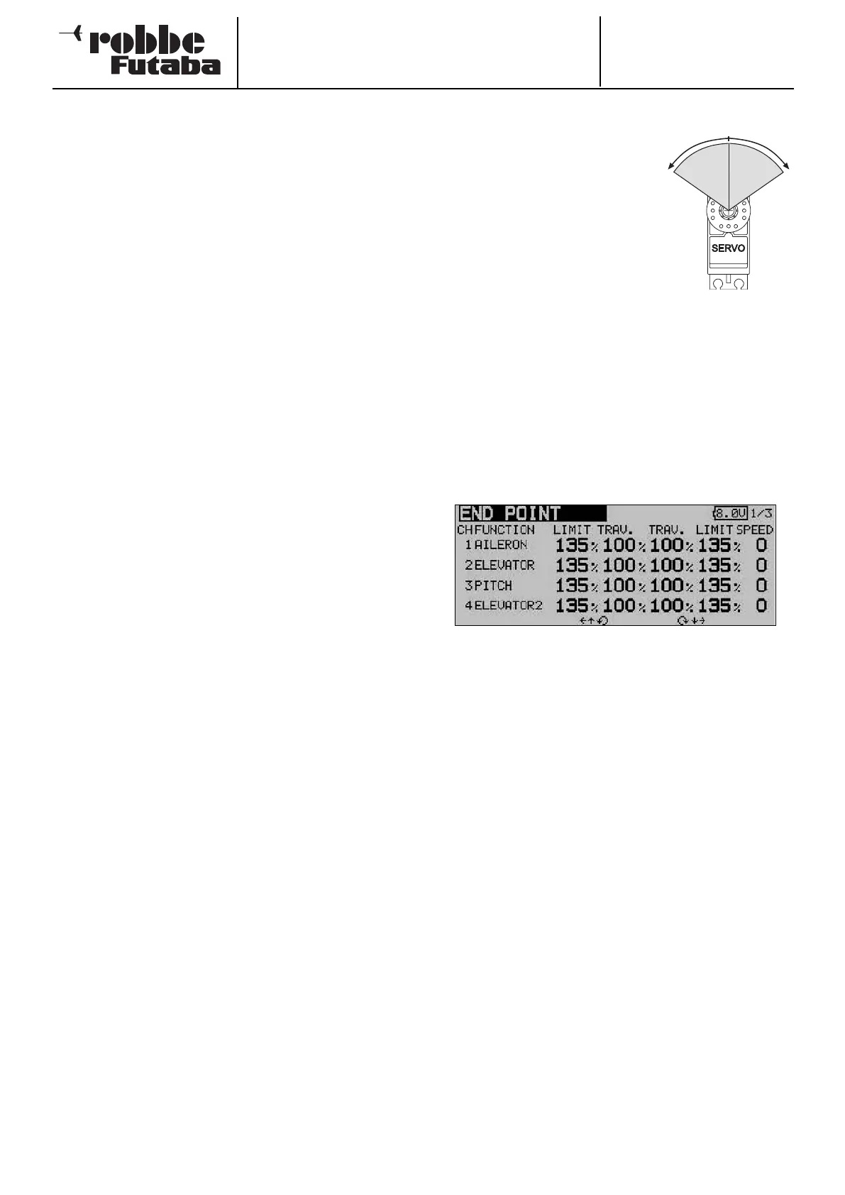
12.9 SERVO TRAVEL SETTINGS (ENDP. ATV)
This function provides a means of
adjusting servo travel separately for
each side of centre, individually for
all twelve channels. It is often neces-
s
ary to reduce servo travel in order
to prevent the servo output shaft
moving through an angle greater
than that permitted by its mechani-
cal limits. However, servo travel can
also be increased for particular
applications. This function always
acts upon the individual servo channel you select, and all
mixed functions involving this channel. In the same menu you
c
an also enter a servo travel limit point and the desired servo
transit speed for each channel separately.
Please note that any changes you make to this setting also
have a proportional effect on the trim travel, as well as on any
Dual Rate settings you have programmed.
Use the 3-D hot-key to mark the ‘Limit’ option in the Base
menu, and confirm your choice with EDIT. The screen now
looks like this:
• Servo travel settings
In the “Travel” column mark the appropriate field for right
or left travel of the servo; this field is now highlighted (dark
background). At this point you can change the servo travel
using the ‘3-D hot-key’ as a % value, corresponding to the
requirements of your model. If you wish to alter the travel
setting for both directions, you have to remember to chan-
ge the value in the ‘Travel’ column. The default setting is
100%, and the travel can be adjusted within the range
30% to 140%. Holding the ‘EDIT’ button pressed in for at
least one second restores the default setting.
• Entering limit points
The same procedure is used for determining the servo limit
point: mark the appropriate field with the cursor, and set
the value using the ‘3-D hot-key’. The limit points can also
be entered individually for each side of servo travel. The
default value is 135%, but the limit point can be varied wit-
hin the range 0 to 155%. Holding the ‘EDIT’ button pres-
sed in for at least one second restores the default setting.
• Entering servo transit speeds
If you wish to adjust the servo transit speed to meet parti-
cular requirements, mark the appropriate field in the right-
hand column using the 3-D hot-key. You can now adjust
the servo speed in single increments within the range 0 to
27 increments, again using the ‘3-D hot-key’. The default
value is 0 increments. Holding the ‘EDIT’ button pressed in
for at least one second restores the default setting.
34
30-140%
l
eft
30-140%
r
ight