Order No.
35 MHz: F 8042
40 MHz: F 8043
41 MHz: F 8044
FX-30
15.2 THROTTLE CURVE SETTINGS
Operating the throttle stick moves the throttle servo, but also
automatically operates the collective pitch servos. The inter-
action between collective pitch and throttle is very important,
and for this purpose the throttle function can be assigned one
of six possible curve types, each of which can be allocated a
maximum of seventeen variable points. The FX-30 also offers
s
witchable flight modes which enable the pilot to set up the
optimum throttle curve for each individual flight mode.
Use the 3-D hot-key to mark the ‘THROTTLE CURVE’ function
in the Helicopter Model menu, and confirm your choice with
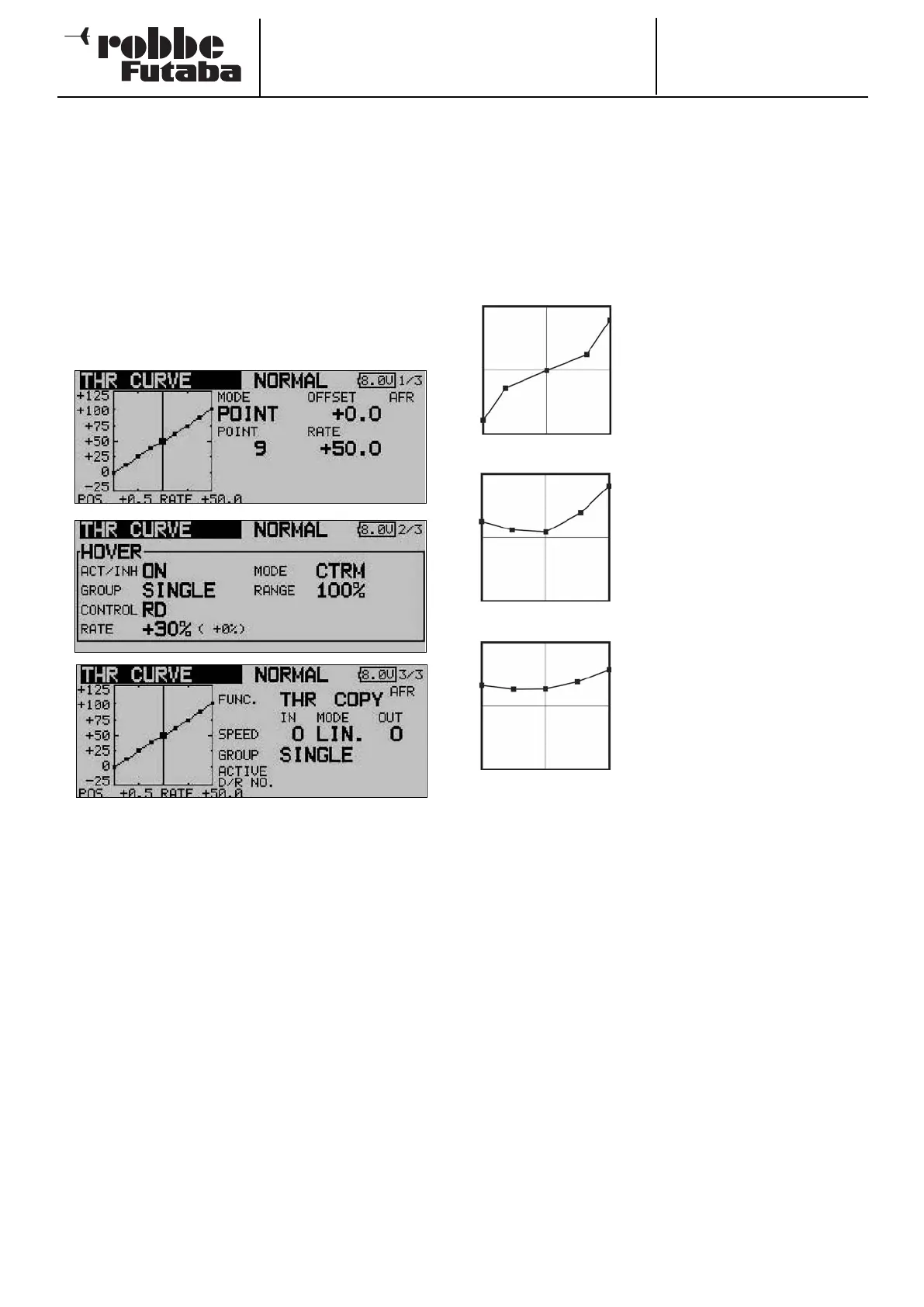
EDIT. The screen has three levels (pages), which look like this:
In this menu you can set up collective pitch curves for the fol-
lowing flight modes:
• Normal: For starting and stopping the motor
• Idle up1 = Throttle pre-select 1: for hovering
• Idle up2 = Throttle pre-select 2: for cruising
• Idle up3 = Throttle pre-select 3: for aerobatics
• HOLD = Auto-rotation: auto-rotation landing
• Condit 6 - 8 = Flight modes 6 to 8: freely selectable
To be able to set different throttle curves it is essential to
switch each flight mode from group mode (GLOBAL) to single
mode (SEPARATE).
Switching between these curves (flight modes) is carried out
using the (flight mode-) switch assigned to the flight mode in
question (see Section 13.1, page 40). When you switch the
s
ystem on, the ‘Normal’ flight mode must be selected, other-
wise you will hear an audible mixer alarm. It is only possible to
switch RF transmission on when the transmitter is set to ‘Nor-
mal’ mode.
Example of a throttle curve for the
‘NORMAL’ flight mode. The curve
should be programmed in such a way
that motor speed remains as nearly
c
onstant as possible over the full
range of travel when the collective
pitch stick is operated. For most pur-
poses five-point curves are perfectly
adequate for this.
Example of a curve for the flight mode
‘Idle up 1’: the values have been opti-
mised for the hover, so that the motor
maintains the correct rotational speed
(rpm) at all collective pitch settings.
For most purposes five-point curves
are adequate are this.
Example of a curve for the flight mode
‘Idle up 2’: the base curve is linear, but
the values have been optimised for
cruising (circuits), so that the motor
maintains the correct rotational speed
(rpm) at all collective pitch settings.
For most purposes five-point curves
are adequate for this.
The curves shown above are just examples. It is essential to
optimise them to suit your specific model by carrying out a
test-flight programme.
The procedure for programming a throttle curve for the indivi-
dual flight modes is absolutely identical to that for setting up
the collective pitch curves. Please read the previous section
on page 62 for a full description.
The same applies to programming the settings for throttle
servo trim in hover mode on the second display page.
The settings for the throttle servo in the third display level are
also completely identical; full details are to be found on page
62.
64