Order No.
35 MHz: F 8042
40 MHz: F 8043
41 MHz: F 8044
FX-30
To be able to set different collective pitch curves it is essenti-
al to switch each flight mode from group mode (GLOBAL) to
single mode (SEPARATE).
Switching between these curves (flight modes) is carried out
using the (flight mode-) switch assigned to the flight mode in
question (see Section 13.1, page 40). When you switch the
system on, the ‘Normal’ flight mode must be selected, other-
wise you will hear an audible mixer alarm. It is only possible to
s
witch RF transmission on when the transmitter is set to
‘Normal’ mode.
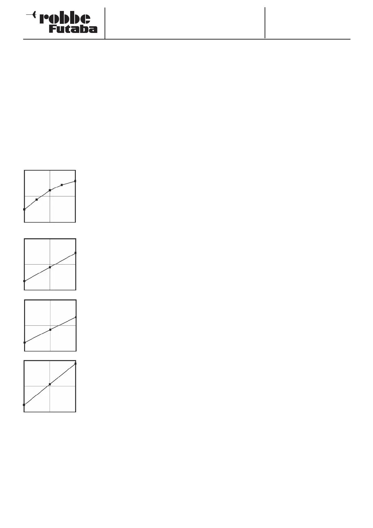
Example of a collective pitch curve for the ‘NORMAL’ flight
mode. The base curve is a straight line. The curve should be
programmed in such a way that the motor speed remains as
nearly constant as possible over the full range of travel. For
most purposes five-point curves are perfectly adequate for
this.
Example of a curve for the flight mode
‘Idle up 1’: the base curve is linear, but
the values have been optimised for the
hover, so that the motor maintains the
correct rotational speed (rpm) at all
collective pitch settings. For most pur-
poses three-point curves are adequate
for this.
Example of a curve for the flight mode
‘Idle up 2’: the base curve is linear, but
the values have been optimised for
cruising (circuits), so that the motor
maintains the correct rotational speed
(rpm) at all collective pitch settings.
For most purposes three-point curves
are adequate for this.
Example of a curve for the flight mode
‘Auto-rotation’: the base curve is line-
ar. For a ‘HOLD’ curve the motor is
switched off, or set to Idle; see the
‘THR-HOLD’ menu (Section 15.4).
The bottom collective pitch value has
been reduced in order to maintain as
high a rotor head speed as possible as
the helicopter falls. The minimum value
has been increased in order to flare
and land the model as smoothly as
possible at a high pitch angle.
The curves shown above are just examples. It is essential to
optimise them to suit your specific model by carrying out a
test-flight programme.
The programming procedure is as follows for all flight modes:
• Programming collective pitch curves
The curve is programmed in the usual way in the first menu
level: first you have to determine the curve type. Mark the
‘MODE’ field in the topmost display, and make your sele-
ction using the ‘3-D hot-key’. The settings are entered in
exactly the same way as for programming the Dual Rate
curves; please read Section 15.1 on page 62 for more
details.
• Trimming the collective pitch function
The collective pitch trim can be optimised in the two
screen levels 2 and 3. On the second page just the trims
for hovering (HOVER) are adjusted. The first step as always
is to mark this option and activate it: mark the field with the
cursor, activate the function with the ‘3-D hot-key’, and
c
onclude the procedure with EDIT. You can now define
whether the settings are to apply to all flight modes
(Global) or only to individual flight modes (Separate).
• At this point you should define a transmitter control for
varying the trim. Mark the ‘Transmitter control’ field using
the 3-D hot-key and activate it with EDIT; this action calls
up the Transmitter Control Select menu; you can now
choose your preferred transmitter control using the proce-
d
ure already described many times.
• Next you define the collective pitch trim mode in the
‘MODE’ field. The options here are ‘NORM’ and ‘CTRM’. If
you select the Normal trim type, the trim range lies sym-
metrically around the centre position, and the servo end-
points are affected when the trim value is changed. The
Centre trim type also works around the centre position of
the transmitter control, but does not affect the end-points,
i.e. the trim travels become asymmetrical when you offset
the trim.
• It is also possible to adjust the trim range (Range). If you
select a small range, the trim only affects the area around
the centre of the stick travel. The final point to adjust is the
trim rate (RATE) or trim travel: the adjustment range is infi-
nitely variable between -30% and +30% of transmitter
control travel; the default setting is +30%. Mark and acti-
vate this option, then turn the ‘3-D hot-key’ to set your pre-
ferred percentage value. Holding the ‘EDIT’ button pressed
in for at least one second restores the default setting
(+30%).
• On the third page of the menu the trims for ‘Collective pitch
minimum’ and ‘Collective pitch maximum’ can be set, i.e.
the end-points of the collective pitch servo travel. The pro-
gramming procedure is exactly the same as that for defi-
ning the hover trim settings, although in this case the trim
mode and trim range are not variable.
• Collective pitch servo settings
• In the fourth level of the menu the most important point to
note is that you can determine the speed and mode of the
collective pitch servo, as well as define whether the curve
is to apply only to the current flight mode (Separate) or to
all flight modes (Global).
• The first facility is for programming a mode: linear mode is
used for controlling non-self-neutralising functions, where-
as symmetrical mode is employed for self-neutralising
functions. A transit speed can be entered separately for
both directions of running, i.e. ‘there’ and ‘back’. The
adjustment range is 0 to 27 increments: the higher the
number, the more slowly the servo moves. The maximum
delay time (27 increments) corresponds to a servo transit
time of nine seconds. The settings are changed using the
‘3-D hot-key’. The default setting is always ‘0’; holding the
‘EDIT’ button pressed in for at least one second restores
the default setting.
63