Order No.
35 MHz: F 8042
40 MHz: F 8043
41 MHz: F 8044
FX-30
14. MODEL MENU (FIXED-WING MODEL AIRCRAFT)
In this Section we analyse the settings which are specific to
fixed-wing model aircraft. The options covered here are those
which have not already been discussed in Section 13 (see
page 41). The model must be marked in the HOME menu, and
confirmed with ‘EDIT’. This calls up an overview of the Model
menus for fixed-wing model aircraft.
• AIL. DIFF: Aileron differential
• FLAP SETTINGS: Flap settings
• SPOILER: Aileron -> spoiler mixer
• AIL->BRAKEFL: Aileron -> brake flap mixer
• AIL->RUD: Aileron -> rudder mixer
• AIRBRAKE->ELE: Airbrake -> elevator mixer
• RUDDER->AIL: Rudder -> aileron mixer
• CAMBER MIX: Flap mixer
• ELE->FLAP: Elevator -> flap mixer
• FLAP->ELE: Flap -> elevator mixer
• BUTTERFLY: Crow (butterfly) mixer
• TRIM MIX 1/2: Trim mixer 1 and 2
• AIRBRAKE: Brake flap mixer
• GYRO: Gyro settings
• V-TAIL: V-tail settings
• AILVATOR: Elevator with aileron function
• WINGLET: Winglet rudder settings
• MOTOR: Settings for electric motors
• RUDDER->ELE: Rudder -> elevator mixer
• SNAP ROLL: Snap-roll function
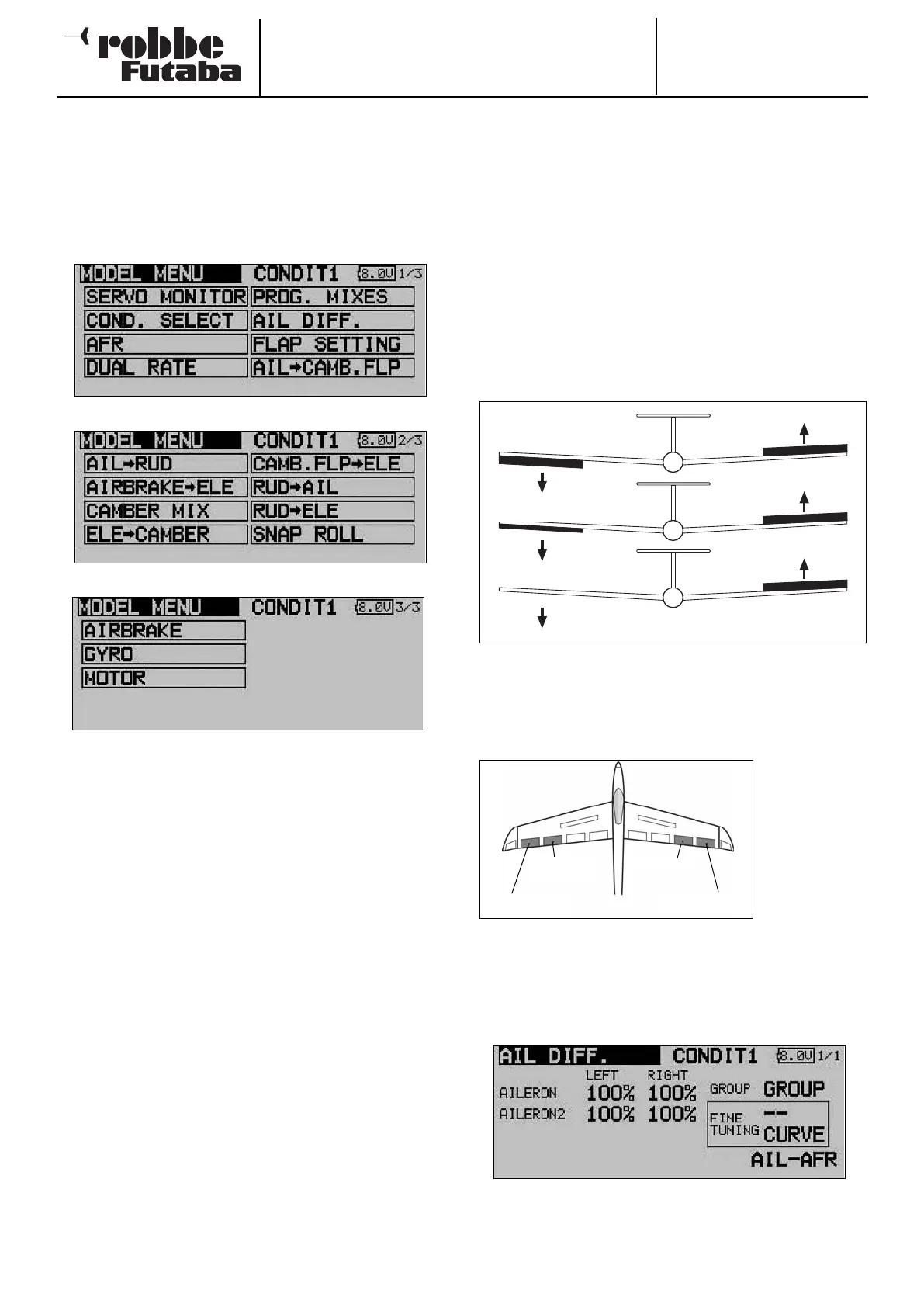
14.1 AILERON DIFFERENTIAL
Differential aileron travel is often required on fixed-wing model
aircraft in order to compensate for the phenomenon known as
adverse yaw. When an aeroplane is turning, the outboard wing
moves through the air more quickly, which means that the
d
rag generated by the down-going aileron (on the outside of
the turn) is greater than that of the up-going aileron. The result
is a yawing moment which tends to turn the model’s nose
away from the turn, swinging the aeroplane around its vertical
axis.
The effect of aileron differential is to reduce the travel of the
down-going aileron relative to that of the up-going aileron, with
the aim of generating equal amounts of drag on both wing
p
anels. This eliminates the adverse yaw problem.
This function acts as a mixer for two separate aileron servos,
enabling you to adjust travels for ‘aileron up’ and ‘aileron
down’ individually for each aileron. One of the auxiliary trans-
mitter controls can be set up as a means of fine-tuning the
degree of differential.
A separate
servo must be
used for each
control surface.
The FX-30 soft-
ware allows
you to assign
transmitter
controls in any
way you like.
The diagram above shows a typical fixed-wing model with two
ailerons on each wing panel.
Use the 3-D hot-key to mark the ‘AIL DIFF.’ option in the Model
menu and confirm your choice with EDIT. The screen now
looks like this:
47
No differential
50% differential
100% differential (split)
Aileron 1
Aileron 3 Aileron 4
Aileron 2