Order No.
35 MHz: F 8042
40 MHz: F 8043
41 MHz: F 8044
FX-30
First determine the ‘Slave’ channel or channels, i.e. the chan-
n
el into which a fixed value is to be mixed. Up to four functions
can be operated in this way. The functions can be selected
o
nce you have marked the corresponding field in the Function
S
elect menu which now appears. Mark the desired function,
a
nd leave the sub-menu by selecting ‘End’.
Y
our selection is displayed in the ‘Slave’ column.
After this the mode of the Offset mixer can be changed if
required. Two modes are available;
M
anual control:
When you operate the switch, the servo runs to the Offset
p
osition selected under ‘ON’, at the set speed and with the set
d
elay, and remains there as long as the switch is in the ‘On’
p
osition. The servo only moves again when the switch is
m
oved back to the ‘Off’ position; it then returns to the starting
p
oint - as set under ‘OFF’ - using the selected speed and
delay.
Timer control:
in this mode the servo runs to the prescribed ‘On’ position, as
described for manual control, when the switch is operated.
However - in contrast to manual control - it does not stay in
this position, but automatically returns to the starting point
when the pre-set dwell time (duration) has elapsed.
This Offset mixer is very convenient, and can be used to
implement sequences involving up to four functions, either
under manual or automatic control. Typical practical applica-
tions include the sequential retraction and extension of a scale
retractable undercarriage, whose functions can be controlled
very accurately using an Offset mixer. By setting the times
carefully, you can arrange for various wheel doors to open in
turn, after which the wheels then extend.
The Offset value can be entered as a percentage figure in the
‘Offset’ fields, separately for the ‘On’ and ‘Off’ states: mark the
appropriate field, and adjust the settings in the familiar way
using the arrow buttons. The adjustment range is +300% to -
300%. The default setting is 0%; marking the ‘Reset’ button
restores the defaults.
Fine-tuning is also available for the Offset mixers. The first
step is to define a transmitter control in the appropriate col-
umn, using the Transmitter Control Select menu as previously
described. After this you must set the effect range in the ‘Rate’
field using the arrow buttons; the adjustment range is +100%
to -100%. The default setting is 0%; marking the ‘Reset’ but-
ton restores the defaults.
The transmitter control you select for fine-tuning an Offset
mixer also has four operating modes; they are absolutely iden-
tical to those of a normal mixer.
You may also wish to optimise the servo transit speed for the
task in hand: the speed of the servo can be adjusted in small
increments, separately for the ‘there’ and ‘back’ directions.
The adjustment range is 0 to 27 increments. Please note: the
higher the number, the more slowly the servo moves. The
maximum value (27 increments) corresponds to a duration of
nine seconds. The default setting is always ‘0’. When you mark
one of the fields ‘THERE’ or ‘BACK’, the button fields for the
arrows appear at the right margin. It is possible to make
adjustments in steps of one increment or ten increments.
Pressing the ‘Reset’ button restores the default setting.
A delay time can be programmed using virtually the same pro-
cedure.
Delays in the range 0.0 to 9.0 seconds can be set, separately
for the ‘Start’ and ‘Stop’ phases.
Pressing the double-arrow buttons increases or reduces the
d
elay by one second; operating the single-arrow buttons pro-
d
uces increments of 0.1 second.
T
he programming of an Offset mixer is concluded by activat-
ing a switch using the standard procedure: mark the corre-
sponding button field in the bottom line, and define the switch
in the Switch Select menu which then appears. The direction
of effect of the switch can also be set in the usual way. The
status of the mixer is displayed as ‘On’ or ‘Off’ - according to
the position of the switch - in the left field in the bottom line.
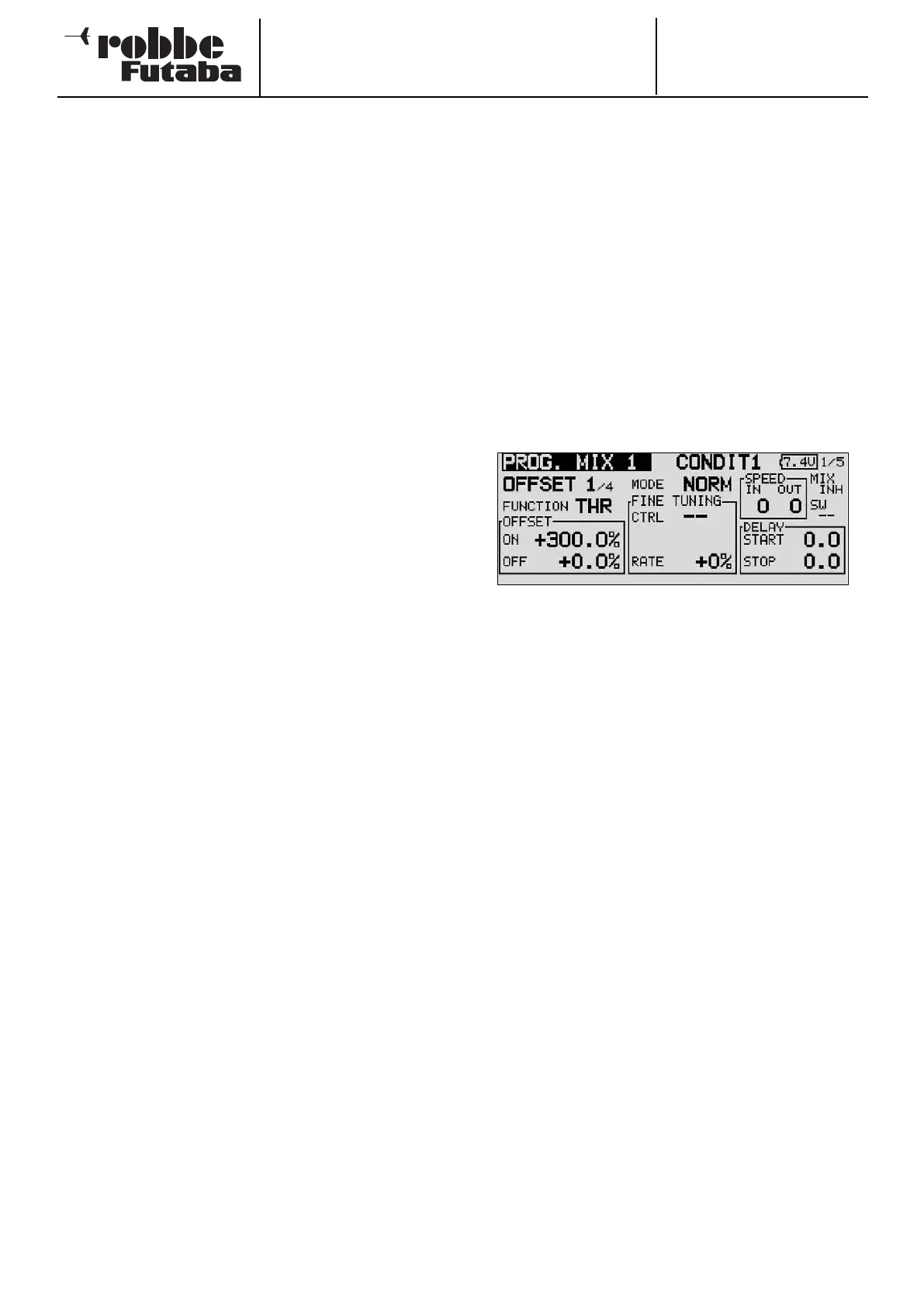
OFFSET MIXER AS MOTOR-CUT SWITCH
Offset mixers also offer the possibility of mixing a fixed value
i
nto the primary channel. This value can be up to 300%, as
shown in the screen shot.
This facility can be used, for example, to make absolutely cer-
tain that the motor of an electric-powered model cannot burst
into life unexpectedly, even if you move the throttle stick by
mistake; this is a very useful safety feature.
If you program an Offset mixer, and set the Offset value to -
300%, the throttle stick can be moved to any position without
the motor starting, because it is impossible for the stick travel
to override the value set by the Offset mixer.
The motor can then only be controlled in the normal way if you
first disable the Offset mixer by operating the associated
switch. This switch is not interrogated during the safety switch
query when the transmitter is switched on.
46