Order No.
35 MHz: F 8042
40 MHz: F 8043
41 MHz: F 8044
FX-30
• If the ‘Link’ function is switched on, the second mixer will
affect the existing mixer, with the result that both aileron
channels will be affected.
• The Link mode can be switched from ‘OFF’ (default) to ‘+’
or ‘-’; the prefix indicates the direction of effect. Changes
are made by turning the ‘3-D hot-key’.
•
Finally you can set up the trim function. Here you have to
determine how the trims of the two mixed channels are to
work. In the corresponding ‘TRIM’ window you can set
‘OFF’ or ‘ON’. If set to ‘ON’, the trim of the Master channel
also affects the Slave channel. Otherwise both channels
are de-coupled. The mode change is carried out using the
‘3-D hot-key’ once the field has been marked; confirm your
choice with the ‘EDIT’ button.
•
Setting up the Slave channel
The settings are entered using exactly the same procedu-
re: mark the ‘Slave’ field, use the ‘3-D hot-key’ to determi-
ne the Slave function, then confirm your choice with EDIT.
Activate the ‘Link’ mode if required, as described above.
• Now you have to determine whether AFR mode is to apply
to the Slave channel, i.e. what is known as ‘Stick to stick
mode’.
• ‘STK - STK’ = OFF
The Master function affects the Slave channel directly,
without taking into account any special settings you may
have applied to the Master transmitter control, i.e. it only
affects the selected Slave channel.
• ‘STK - STK’ = ON
In this mode any special settings applied to the Master
transmitter control - such as D/R, AFR, EXPO etc. - also
affect the Slave channel. In this mode the mixer functions
also affect any other mixers involving the Slave channel.
Example: Model type - two ailerons
Mixing elevator to aileron in ‘Stk - Stk’ mode affects both
ailerons.
Select the mode accordingly, and - if necessary - switch the
mode from ‘OFF’ to ‘ON’ by turning the ‘3-D hot-key’.
Pressing the ‘EDIT’ button concludes the procedure.
• Carrying out ‘fine-tuning’ adjustments
It is possible to program a transmitter control which is used
to carry out fine adjustments (fine-tuning) of the mixer set-
tings. Changes are carried out in the ‘TRIM’ line, but first
you have to define the transmitter control you wish to use
for this purpose: mark the appropriate field to call up the
menu, then select your preferred transmitter control using
the ‘3-D hot-key’. Any of the auxiliary transmitter controls
can be used.
Next you have to define the operating mode for the trans-
mitter control you have chosen; the mode is selected using
the standard procedure: mark the ‘Mode’ field using the 3-
D hot-key, and make your selection using the ‘3-D hot-key’
once more. Four modes are available in total, and their
method of working is displayed on-screen in schematic
form. This is the key to the symbols:
The mixer rate is 0% when the transmitter control
is in the centre position. Moving the transmitter
control to right or left increases and reduces the
value respectively.
The mixer rate is 0% at the left end-point of the
transmitter control. Moving the transmitter control
to the right increases the value.
The mixer rate is 0% at the right end-point of the
transmitter control. Moving the transmitter control
to the left increases the value.
T
he mixer rate is 0% when the transmitter control
is in the centre position. Moving the transmitter
control to right or left always increases the value.
• Setting the servo transit speed and delay
In the ‘SPEED’ line you can enter a speed for both dire-
ctions of servo travel, i.e. the ‘there’ direction and the
‘back’ direction. The adjustment range is 0 to 27 incre-
ments. Please note: the higher the number, the more slow-
l
y the servo moves. The maximum value (27 increments)
corresponds to a duration of nine seconds. The value is
changed using the ‘3-D hot-key’. The default setting is ‘0’.
Holding the ‘EDIT’ button pressed in for at least one
second restores the default setting.
In the ‘Delay’ line you can enter a delay time in the range
0.0 to 4.0 seconds for the POWER ON and POWER OFF
phases. This value means the time which elapses between
operating the switch (in the ‘ON’ direction), and the mixer
taking full effect. In the ‘STOP’ field you can program a
delay which occurs when the mixer is switched off again.
To program this setting you must first mark the appropria-
te field and enter the setting using the ‘3-D hot-key’. The
default value is ‘0’. Holding the ‘EDIT’ button pressed in for
at least one second restores the default setting.
• Master / Slave function
The Master / Slave function is used to control pre-set and
programmed curves using a switch.
In Slave mode you can define a target point which is rea-
ched after a user-defined time. This function only takes the
end-point into account - not any intermediate points. In
Master mode the situation is different: in this case you can
set up a curve with seventeen intermediate points, all of
which are taken into account when the function is switched
on. This means that you can give your model aircraft a
completely new set-up within a few seconds, or change its
characteristics to suit particular circumstances.
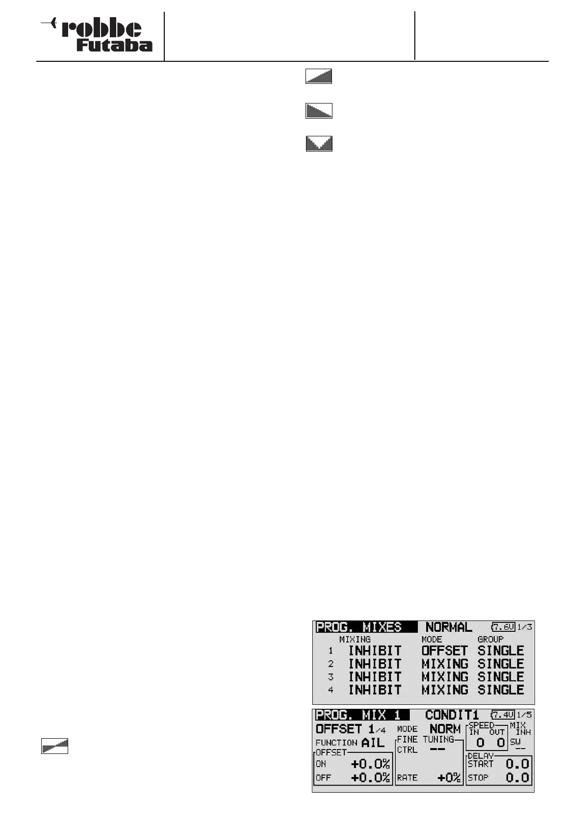
• Programming an Offset mixer
This type of mixer is typically used to pass a fixed value to
a particular function when the mixer is triggered by opera-
ting a switch. This means that Offset mixers do not require
a Master channel.
To activate this function simply change the mode from
MIXER to OFFSET.
45