The mixer rates are set in the main Crow menu for the (max.)
four aileron and flap servos, according to the selected model
or wing type, using the familiar method. Starting from this main
menu, you can use the switch fields at the bottom of the
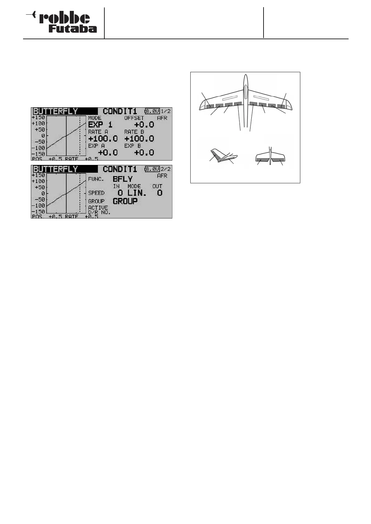
screen to move to the set-up menu for Butterfly AFR (D/R)
curve for this mixer (screen 4) and to the programming menu
for the associated elevator travels (screen 5). Pressing the S1
button takes you to the two sub-menus (screens 2 and 3).
The Crow mixer must first be activated in the ‘ACT / INA’ line
on the second screen: first mark the field, enter the settings
using the ‘3-D hot-key’, and conclude the activation with EDIT.
The field will now display ‘ON’ or ‘OFF’ according to the posi-
tion of the switch.
The effects and settings for the programming of ‘Global’ or
‘Separate’ mode have already been described repeatedly;
they are entered in the ‘Mode’ line. In the ‘Switch’ line a switch
can be selected in the familiar manner, and its direction of ope-
ration determined. The default setting here is ‘NONE’, i.e. the
mixer is always switched on. In the ‘Offset’ line a reference
point can be entered as a % value. Select the reference point
for this mixer, and confirm your choice with the ‘EDIT’ button.
On this second page you can also set the servo speed indivi-
dually for the aileron and flap servos, using the now familiar
method, in each case separately for the ‘there’ and ‘back’ dire-
ctions. On the third menu screen you can set the % value for
aileron differential, and program a delay time.
The AFR or D/R mixer curve can be selected in the usual man-
ner, and the mixer rates entered separately for both sides (see
screen 4). The last menu page includes a point for program-
ming a suitable elevator travel; this is intended for pitch trim
compensation. The servo speed can also be entered for up to
two elevator servos.
Please note that the programming options and the actual
appearance of the screen displays may vary slightly according
to the model type and wing type you have selected.
14.12 TRIM MIXER 1 AND 2
This menu is used to set up mixers which apply to all the wing
control surfaces and the elevators, separately for particular
flight phases.
The software of
the FX-30 provi-
des two flight
p
hase mixers
(TRIM MIX 1 and
2); both mixers
are programmed
in exactly the
same way, so
this section only
describes the
set-up proce-
d
ure for the first
mixer.
A typical application would be for a model glider, with TRIM
MIX 1 set up to provide the optimum control surface settings
for the winch launch phase of the flight. These settings would
lower the ailerons and the flaps in order to maximise the
model’s lift on the winch line. To ensure a stable pitch attitude
on tow, the mixer includes an option for entering an elevator
Offset to provide pitch trim compensation (i.e. around the late-
ral axis).
In our example the second mixer (TRIM MIX 2) might be used
to set up the optimum control surface settings for the speed
phase of the flight, with ailerons and flaps raised slightly in
order to minimise the aircraft’s drag.
These options are designed to ensure that reliable, reproduci-
ble control surface travels can be recalled again and again
when you select these flight phases. You can assign any
switch you like for calling up the settings.
An Offset can be entered for each of the wing control surfaces
- up to four ailerons and four flaps - in order to fine-tune the
individual wing flap neutral positions (screens 1 to 3). You can
also assign one of the auxiliary transmitter controls for fine-
tuning the system. This allows you to select pre-set positions
for all the control surfaces prior to fine-tuning in flight. As with
all mixers, you can select ‘Global’ or ‘Separate’ mode as requi-
red.
You can also define a trigger switch which activates the set-
tings for the flight phase. At the same time you can determine
whether the function is triggered by a switch (manual mode) or
by the position of a transmitter stick (automatic mode).
It is possible to set the required transit speed individually for
the aileron servos, flap servos and elevator servos, with sepa-
rate settings for the ‘there’ and ‘back’ directions. If you wish,
you can program a delay time for this mixer function, so that
the transition is smooth rather than abrupt.
Start by using the 3-D hot-key to mark the desired ‘TRIM MIX
1’ or ‘TRIM MIX 2’ option in the Model menu, and confirm your
choice with EDIT. The menu has five levels (pages), which look
like this:
Order No.
35 MHz: F 8042
40 MHz: F 8043
41 MHz: F 8044
FX-30
55
Chip
aileron
(AIL3)
Main
aileron
(AIL1)
Camber-
changing
f
lap
(
CAMBER1)
C
amber-
changing
flap
(CAMBER2)
Brake flaps
(BRFL3 & 4)
Main
aileron
(AIL2)
Chip
aileron
(AIL4)
V-tail Ailvator
ELE
ELE
RUDD
ELE2