Order No.
35 MHz: F 8042
40 MHz: F 8043
41 MHz: F 8044
FX-30
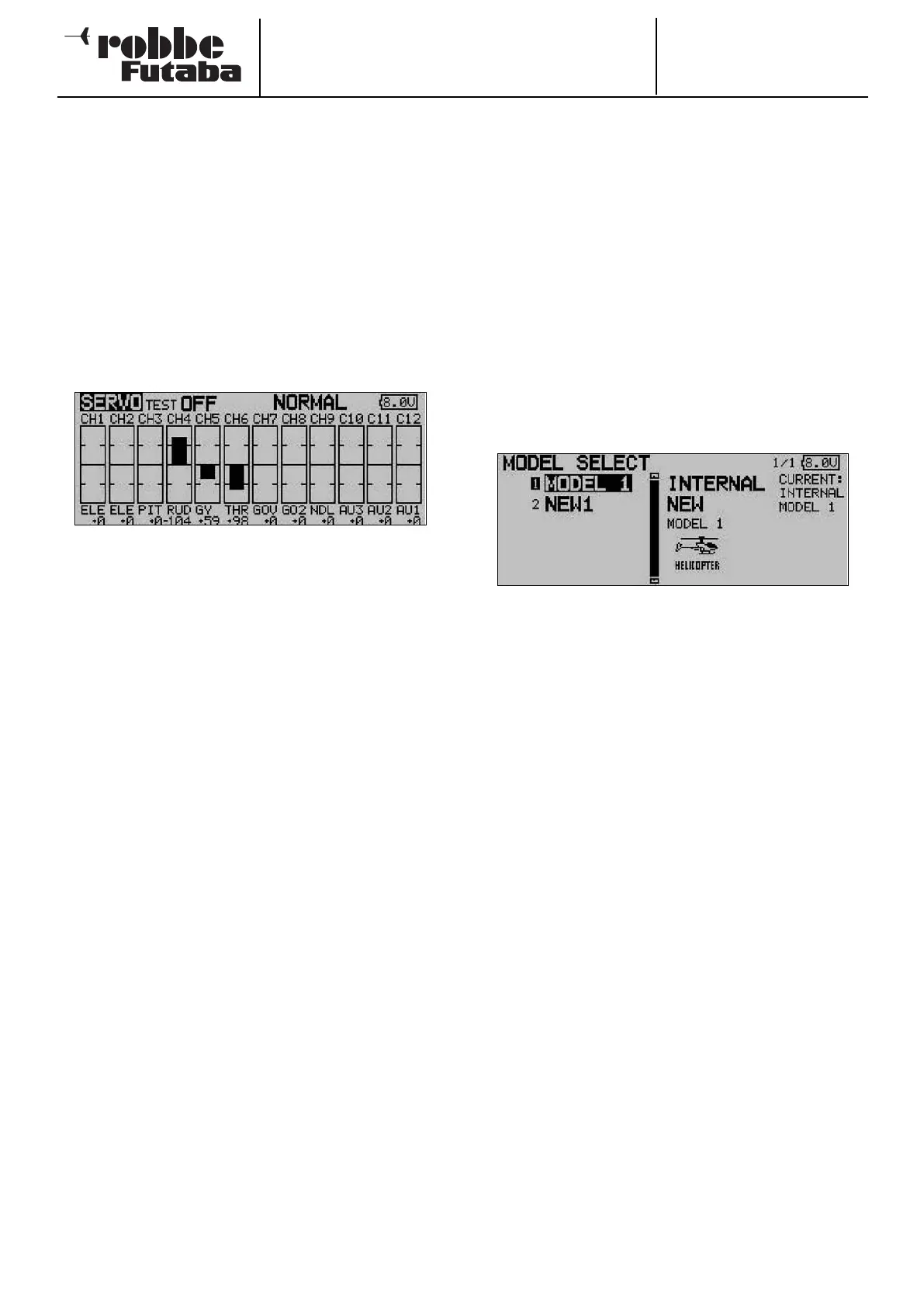
12.1 SERVO MONITOR
The Servo Monitor menu displays all servo travels in a clear
form using a bar graph and percentage values. The travels are
those which are generated by all the adjustments and mixer
functions which you have set up. This constitutes an ideal test
program for checking control surface travels manually, or for
testing all servos automatically.
Note:
The servo monitor takes into account all the adjustments you
may have made, including Limit, transmitter control travel etc.
Use the 3-D hot-key to mark this option in the Base menu, and
confirm your choice with EDIT.
There are three different modes available in the servo monitor:
• Servo test ‘Off’
In this mode the screen displays the servo travels / posi-
tions corresponding to the current transmitter control posi-
tions. A useful tool for manually checking mixer functions
and travel settings for individual servo channels.
Move the desired transmitter control. The Test mode must
be switched off for this (Test Off). The screen displays the
servo deflection for the corresponding channels in bar-
graph form and as percentage values.
• Neutral positions ‘Neutral’
All channels move to the neutral position dictated by the
transmitter. This is an excellent means of checking that
servos and servo output arms are set to accurate neutral
positions. It is also ideal for establishing the neutral posi-
tion when installing servos in a model.
Move the ‘3-D hot-key’ to change the test mode in the
right-hand field from ‘Off’ to ‘Neutral’.
• Automatic servo test ‘Move’
This mode activates an automatic servo test: all channels
are slowly moved from one end-point of the transmitter
control to the other. Ideal for testing servos and checking
maximum control surface travels.
This mode is accessed by switching the Test mode (Move)
on. Select the button using the ‘3-D hot-key’, then switch
the mode on and confirm your choice.
12.2 SELECTING A MODEL MEMORY
This menu enables you to select the actual model memory file
you wish to use. It is also designed for general model data
handling tasks, such as creating new memories, copying, era-
sing and renaming.
Each model memory takes up a space of around 500 kB.
Thirty models can be stored internally, while a 32 MB SD card
can store approximately 60 models. The transmitter supports
SD cards with a maximum capacity of 1 GB = 1958 models.
Note:
We strongly recommend that you create a back-up copy of
your model memory, especially if you wish to experiment with
d
ifferent settings. When you switch off the transmitter, the cur-
rent data is always written to the model memory.
CALLING UP A MODEL MEMORY
• The first step must always be to determine the memory
location
- INTERNAL or
- SD card
Mark the appropriate field, and use the ‘3-D hot-key’ to
select the desired memory medium.
• The left-hand field on the screen displays the list of models
stored on the selected memory medium. The list includes
all the model memories you have created, together with
the model names. Use the 3-D hot-key to mark the desired
model, then press the ‘EDIT’ button.
• A security query appears which you must also confirm with
EDIT: the new model memory is now activated.
• Initially the RF signal is still switched off for reasons of
safety. The screen now displays the query ‘Transmit?’. You
must answer with ‘Yes’; only then is the transmitter ready
for use with the newly selected model memory.
SETTING UP A NEW MODEL MEMORY
• The first step must always be to determine the memory
location
- INTERNAL or
- SD card
Mark the appropriate field and use the ‘3-D hot-key’ to
select the desired memory medium.
• After this you have to re-mark the field and activate it. For
safety reasons the radio link is now interrupted.
• Confirm the subsequent security query with the ‘EDIT’ but-
ton once more.
• A display now appears automatically in which you can:
- select the model type and confirm the change;
- select the spot frequency and modulation and - if neces-
sary - enter the new receiver No.
• Confirm the frequency change. Switch the transmitter off,
then on again, and the radio link is restored.
27