Order No.
35 MHz: F 8042
40 MHz: F 8043
41 MHz: F 8044
FX-30
14.20 SNAP ROLL FUNCTION
The snap roll function enables you to define transmitter control
positions which cause the aeroplane to carry out a particular
flight manoeuvre. The model then flies this manoeuvre when
you operate a switch. The servo settings cannot be overridden
while the switch is in the ‘ON’ position.
F
or each flight manoeuvre it is possible to define four settings
(right / up; right / down; left / up; left / down) for each of the
three primary control surfaces (aileron, elevator and rudder). A
mode (Master or Single) can also be defined, which determi-
nes whether a Master switch or any other switch is to be used
to initiate and conclude the manoeuvre. If you select Master
mode, a safety switch must be defined in addition to the trig-
ger switch (Master switch). The Master switch is then only
active when the ‘safety switch’ is in the ‘ON’ position. The pur-
p
ose of this precaution is to ensure that you never trigger the
snap roll manoeuvre accidentally.
The servo speed of all three control surfaces can be set indivi-
dually, separately for the ‘there’ and ‘back’ directions.
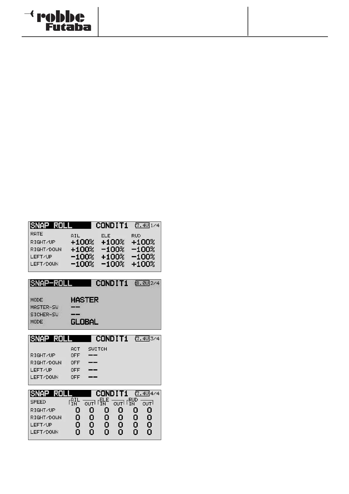
Use the 3-D hot-key to mark the ‘SNAP ROLL’ option in the
Model menu, and confirm your choice with EDIT. The screen
display has four levels (pages), which look like this:
The servo travel can be entered as a percentage value for all
three control surfaces (aileron, elevator and rudder); this is car-
ried out in the first menu level, and is available for each dire-
ction of travel separately.
The familiar method is employed: first mark the field, then
change the value using the ‘3-D hot-key’ before concluding
the process with EDIT.
O
n the second display page you can define the mode - ‘Mas-
ter’ or ‘Single’ - for the trigger process. As already mentioned,
selecting ‘Master’ mode requires you to define a safety switch
in addition to the main trigger switch. Both switches can be
programmed on this page of the menu using the normal pro-
cedure. In the bottom line of the second page you can also set
the ‘Global’ or ‘Separate’ mode as already described, i.e.
whether the function is to be available in all flight modes or
only one flight mode.
At the third menu level you can define a switch for each of the
four directions, again using the normal method: mark the
appropriate field and select the values using the ‘3-D hot-key’.
The activation state in the ‘ACT’ column will now display ‘ON’
or ‘OFF’ according to the position of the switch.
In the final menu level you can set the servo speed for each
direction of movement, separately for the ‘there’ and ‘back’
direction of the servos. As with all servo speed adjustment
facilities, the available range of values is from 0 to 27.
Please be particularly careful when programming this function,
and take care not to enter any settings which could lead to
uncontrollable flight situations. Check everything very care-
fully!
61