Order No.
35 MHz: F 8042
40 MHz: F 8043
41 MHz: F 8044
FX-30
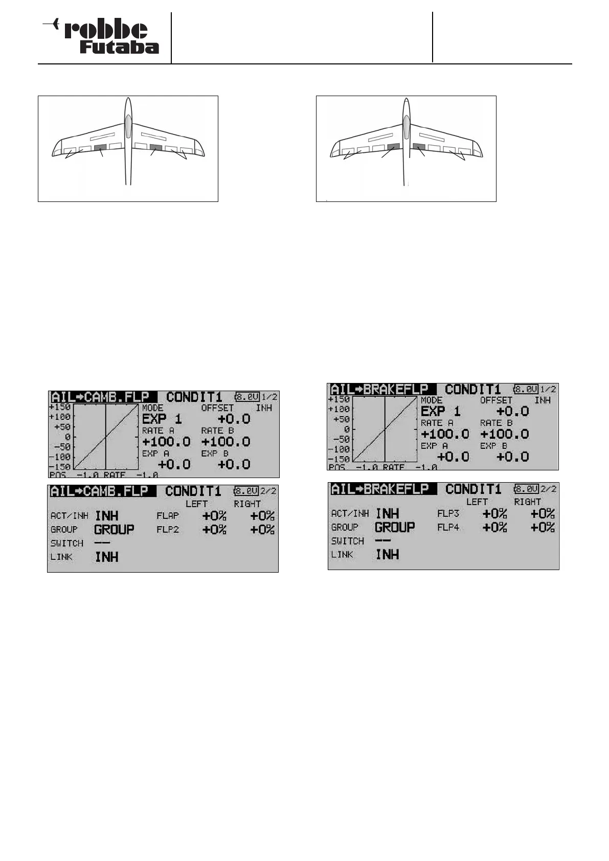
14.3 AILERON -> FLAP MIXER
This menu is
used to set the
values for a
mixer which
causes the
inboard flaps to
m
ove in the
same direction
as the ailerons
when an aileron
command is given. This mixer improves the roll rate of a model
glider, because the flaps deflect to support the ailerons, there-
by generating a greater roll moment. At the same time the
induced drag of the wing is reduced when the model is tur-
ning.
T
he mixer rate can be adjusted in the usual way, but it is also
possible to set up a curve in order to obtain the exact control
surface travel you require. The function can be activated using
a switch which is user-selectable; it can also be connected to
other mixers via a Link.
Use the 3-D hot-key to mark the ‘Aileron -> flap’ mixer in the
Model menu, and confirm your choice with EDIT. The menu
has two levels (pages) which look like this:
Start by activating this function in the ‘ACT / INA’ line using the
familiar method, then enter the mixer values for both flaps as
percentages using the ‘3-D hot-key’ in the standard way, in
each case for left and right aileron deflections. If you need to
reverse the direction of travel, this is achieved by changing the
prefix.
The effects and method of setting the ‘Global’ or ‘Separate’
mode have already been described. If you wish to link this
mixer to the aileron -> brake flap mixer, the appropriate set-
tings should be entered in the ‘LINK’ line. You must first acti-
vate this option, then select a switch to be able to switch this
function on and off. A mixer curve can also be defined and
programmed on the first screen page.
14.4 AILERON -> BRAKE FLAP MIXER
This menu is
used for setting
up a mixer
which causes
t
he brake flaps
to move in the
same direction
as the ailerons
when an aileron
command is
given. This mixer helps to improve the manoeuvrability of a
model aircraft around the longitudinal (roll) axis, because the
flaps deflect to support the ailerons, thereby generating a gre-
a
ter roll moment. At the same time the induced drag of the
wing is reduced when the model is turning.
The mixer rate can be adjusted in the usual way, but it is also
possible to set up a curve in order to obtain the exact control
surface travel you require. The function can be activated using
a switch which you can select; it can also be connected to
other mixers via a Link.
Use the 3-D hot-key to mark the ‘Aileron -> brake flap’ option
in the Model menu, and confirm your choice with EDIT. The
menu has two levels (pages) which look like this:
Start by activating this function in the ‘ACT / INA’ line using the
familiar method, then enter the mixer values for both brake
flaps as percentages using the ‘3-D hot-key’ in the standard
way, in each case for left and right aileron deflections. If you
need to reverse the direction of travel, this is achieved by
changing the prefix.
The effects and method of setting the ‘Global’ or ‘Separate’
mode have already been described. A switch can be selected
to trigger the mixer, using the standard procedure; define its
direction of operation in the usual way.
If you wish to link this mixer to another mixer, the appropriate
settings should be entered in the ‘LINK’ line. You must first
activate this option, then define the mixer to which a link is to
be created.
A mixer curve can also be defined and programmed on the
first screen page.
49
Camber-
c
hanging
flap
(
Camber2)
Ailerons
(Ail2 &
A
il4)
Ailerons
(
Ail &
Ail3)
Camber-
c
hanging
flap
(
Camber)
Brake
flap
(BRF2)
Ailerons
(Ail2 &
A
il4)
Ailerons
(Ail &
Ail3)
Brake
flap
(BRFL)