Order No.
35 MHz: F 8042
40 MHz: F 8043
4
1 MHz: F 8044
FX-30
3. SPECIFICATION
3.1 FX-30 transmitter
Control channels: . . . . . . . . . . . . . . . . . .8 - 12 channels FM
. . . . . . . . . . . . . . . . . . . . . . .10 channels PCM-1024
. . . . . . . . . . . . . . . . . . . .14 channels PCM 2048 (G3)
Frequency bands: . . . . . . . . . . . . . . . . . . . .35 / 40 / 41 MHz
Spot frequencies: . . . . . . . . . . . . . . . . . . . . . . . . . .49, 22, 21
Transmission system: . . . .FM (PPM) or PCM 1024, PCM-G3
C
hannel spacing: . . . . . . . . . . . . . . . . . . . . . . . . . . . .10 kHz
Power supply: . . . . . . . . . . . . . . . .7.4 V LiPo battery / 3.4 Ah
Current drain: . . . . . . . . . . . . . . . . . . . . . . . .approx. 320 mA
Dimensions: . . . . . . . . . . . . . . . . . . . . . . .205 x 220 x 55 mm
Weight (incl. battery): . . . . . . . . . . . . . . . . . . .approx. 1035 g
3.2 R-1410 DP PCM-1024 RECEIVER
No. of channels: . . . . . . . . . . . . . . . . . . . . . . . . . . . . . . . . .10
Frequency bands: . . . . . . . . . . . . . . . . . . . .35 / 40 / 41 MHz
Intermediate frequencies: . . . . . . . . .10.7 MHz and 455 kHz
Transmission system: . . . . . . . . . . . . . . . . . . . . . .PCM-1024
C
hannel spacing: . . . . . . . . . . . . . . . . . . . . . . . . . . . .10 kHz
Power supply: . . . . . .4.8 … 6 Volts (4 … 5 cells, NC / NiMH)
Current drain: . . . . . . . . . . . . . . . . . . . . . . . . . . . . . . .12 mA
Dimensions: . . . . . . . . . . . . . . . . . . . . . . . . .56 x 33 x 21 mm
Weight: . . . . . . . . . . . . . . . . . . . . . . . . . . . . . . . . . . . . . .34 g
6
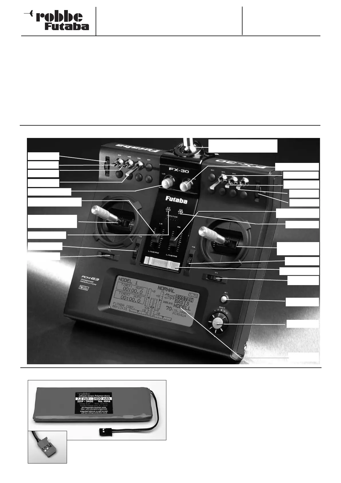
4. FX-30 TRANSMITTER CONTROLS
Switch ‘B’
Switch ‘E’
Switch ‘A’
Monitor-LED
Elevator trim
Aileron trim
‘3-D-Hotkey’
LCD screen
Linear slider ‘LS’
Rudder trim
Throttle trim
On / Off switch
Elevator / aileron
stick
Throttle / Rudder
stick
Switch ‘H’
Switch ‘G’
Switch ‘D’
Aerial base for screw-fitting
telescopic aerial
4.1 LiPo transmitter battery, 7.4 Volt / 3400 mAh, No. 4846
REMOVING / CHANGING THE TRANSMITTER BATTERY
• First switch the transmitter off.
• Remove the RF module.
• Unlatch the back panel at the top and fold it open, taking care
not to damage the lower locating lugs.
• Undo the retaining bands.
• Disconnect the battery connector from the transmitter by pul-
ling on the connector itself (not on the wires).
• When re-installing the battery in the transmitter please note
that the battery lead must face the right.
• Plug in the connector, taking care to maintain correct polarity.
• Re-fit the retaining bands.
• Engage the lower locating lugs of the back panel. Fold the
back panel up into the correct position and engage the top
latch. Ensure that no wires are snagged between the panels.
Input button
Linear slider ‘RS’
Power LED
Trimmer 5
Trimmer 6
Rotary knob ‘RD’
Rotary knob ‘LD’