Order No.
35 MHz: F 8042
40 MHz: F 8043
41 MHz: F 8044
FX-30
56
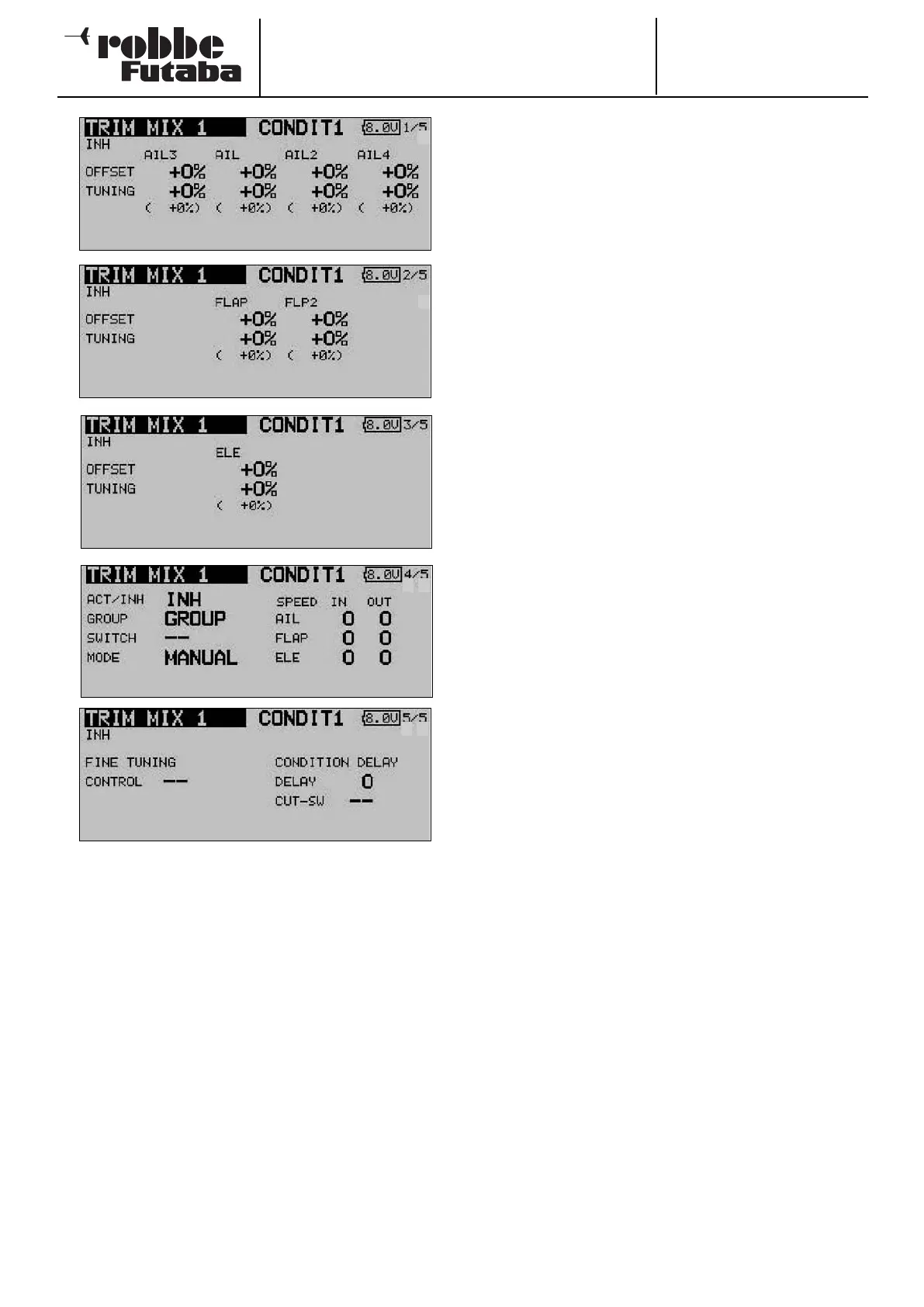
The page indicator on the right-hand side indicates that there
are additional menu levels. In the first three menus the settings
are virtually identical; the difference between them is that the
topmost level contains the settings for the ailerons, the second
page those for the camber-changing and brake flaps, and the
third screen the settings for the elevators.
An Offset value can be entered separately for each control sur-
face, by marking the appropriate field and then entering the
required value using the ‘3-D hot-key’, and confirming your
choice with EDIT. The same technique is employed to set the
fine-tuning values.
The mixer must be activated in the ‘ACT / INA’ line on the
fourth screen: first mark the field, enter the settings using the
‘3-D hot-key’, and conclude the activation with EDIT. The field
will now display ‘ON’ or ‘OFF’ according to the position of the
switch.
The effects and settings for the programming of ‘Global’ or
‘Separate’ mode are entered in the ‘Mode’ line. In the ‘Switch’
line a switch can be selected in the familiar manner, and its
direction of operation determined. The default setting here is
‘NONE’, i.e. the mixer is always switched on.
You can also determine whether the ‘TRIM’ mixer is to be acti-
vated using the selected switch, or automatically by the posi-
tion of one of the sticks. If you prefer the latter automatic
mode, first mark the field and confirm with EDIT. This calls up
a menu in which you can set the desired stick and trigger
point, using the familiar methods.
T
he servo transit speed for all three control surface types
(ailerons, flaps and elevator) can be programmed on the fourth
page of the menu, in each case separately for the servo dire-
ctions ‘there’ and ‘back’.
In the final menu display you can select a transmitter control or
switch for fine-tuning the function: mark the field and confirm
with EDIT to call up the Switch Select menu. You can now
define your preferred transmitter control in the time-honoured
f
ashion.
Finally it is possible to program a delay time using the techni-
que which has already been described repeatedly. One new
feature here is that a switch can be defined which is used to
switch the delay from active to disabled. This means that both
types of transition between flight modes are available accor-
ding to switch position, i.e. abrupt or smooth. The method of
selecting the switch is identical to the usual switch select
method.
Please note that the programming options and the actual
appearance of the screen displays may vary slightly according
to the model type and the wing type you have selected.
5
5
5
5
5
4