Saia-Burgess Controls AG
Manual Manual PCD 1 / PCD 2 Series │ Document 26 / 737 EN22 │ 2013-11-26
4
Communication interfaces
4-29
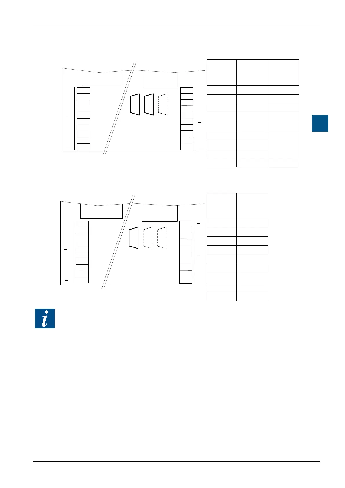
Serial interfaces: socket B(1) or B2
RS-232 to D-Sub connector with PCD2.M170
PCD2.M170
PCD2.F522
B2
B1
B1 B2
#0#5#3
PGU
39
38
37
36
35
34
33
32
31
30
39
38
37
36
34
33
32
31
40
41
42
43
44
45
46
47
48
49
41
42
43
44
46
47
48
49
Port #3
Port #5
Assigne-
ment
RS-232
B1
Port #3
D-Sub Pin
B2
Port #5
D-Sub Pin
PGND 1 1
- 2 2
RxD 3 3
- 4 4
CTS 5 5
RTS 6 6
- 7 7
TxD 8 8
- 9 9
RS-232 to D-Sub connector with PCD2.M170
PCD2.M480
PCD2.F522
B1
Option
B1
S-Net
MPI
COM
PGU
39
38
37
36
35
34
33
32
31
30
39
38
37
36
34
33
32
31
40
41
42
43
44
45
46
47
48
49
41
42
43
44
46
47
48
49
Port #3
Port #5
PCD2.F522
B2
Assigne-
ment
RS-422
B1
Port #3
D-Sub Pin
PGND 1
- 2
RxD 3
- 4
CTS 5
RTS 6
- 7
TxD 8
- 9
The DTR / DSR and DCD control lines are not present on these interfaces. If they
are needed, e.g. to connect a modem, it is advisable to use the PCD7.F120 Module
on socket A (Port # 1) or PCD2.F522 (in RS-232 full mode) on socket B1 / B2.