Saia-Burgess Controls AG
Manual Manual PCD 1 / PCD 2 Series │ Document 26 / 737 EN22 │ 2013-11-26
4
Communication interfaces
4-39
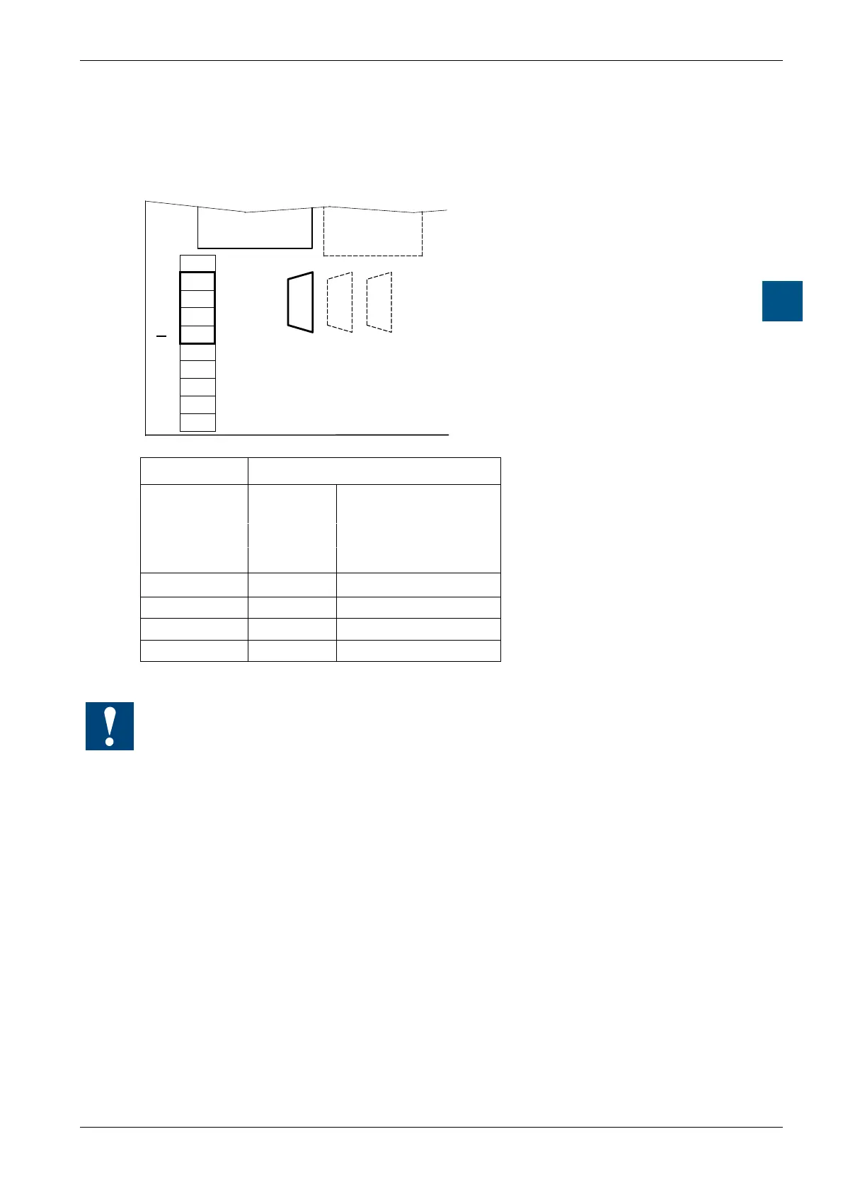
Probus
PCD7.F700 with PCD2.M170
The bus should be connected to the D-Sub connector. The pin conguration is as per
the Probus standard. Alternatively the Probus can be attached to the screw termi-
nal block.
Profibus FMS Client/Server
PCD2.M170
B2
B1
B1 B2 PGU
#FMS #0
#...
39
38
37
36
35
34
33
32
31
30
38
37
36
Profibus FMS
Socket B1 FMS Client / Server
Kind of con-
nection
D-Sub Screw terminal block
9 pole 10 pole
Signal Pin number Terminal number
RxD / TxD-P 3 37
RxD / TxD-N 8 36
PGND 1 35
DP GND 5 38
There are no line termination resistors on this module. It is advisable to use an
external termination box (e.g. PCD7.T160).