Saia-Burgess Controls AG
Manual Manual PCD 1 / PCD 2 Series │ Document 26 / 737 EN22 │ 2013-11-26
5
Input/output (I/O) modules
5-18
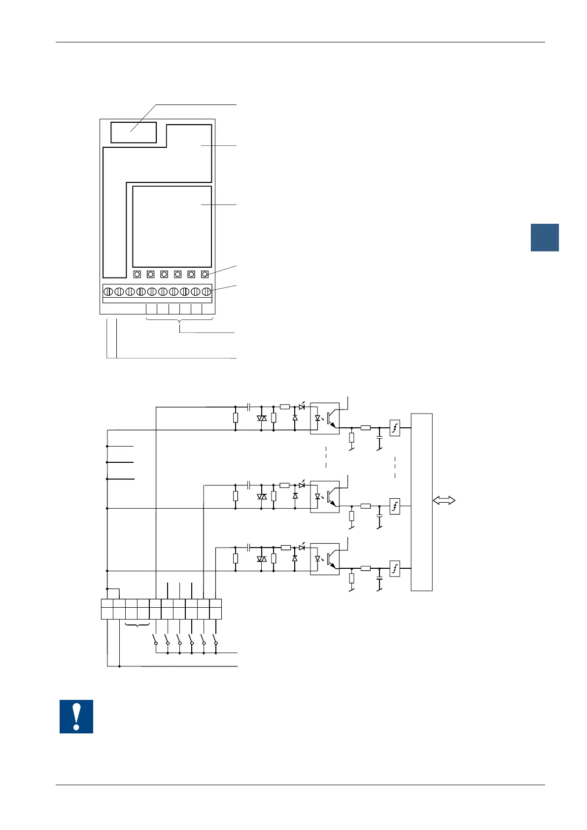
Digital input modules, electrically isolated
LEDs and connection terminals
9 8 7 6 5 4 3 2 1 0
E0E1E2E3E4E5COM COM
Bus interface,
Optocoupler,
threshold switch
Input bleeder chain
LEDs
Screw terminals
Inputs E0 to E5 0 - 5
Common connection
for the 6 inputs
Input circuits and terminal designation
Switch closed: Signal status 'H' = LED on
Switch open : Signal status 'L' = LED off
Phase 115 - 230V 50/60 Hz *)
*) or interchangeable, if the rules permit this
COM
COM
Watchdog: This module can be used on all base addresses; there is no interaction with the
watchdog on the CPUs. For details, please refer to the “Watchdog” section, which describes
the correct use of the watchdog in conjunction with PCD2 components.