Saia-Burgess Controls AG
Manual Manual PCD 1 / PCD 2 Series │ Document 26 / 737 EN22 │ 2013-11-26
5
Input/output (I/O) modules
5-20
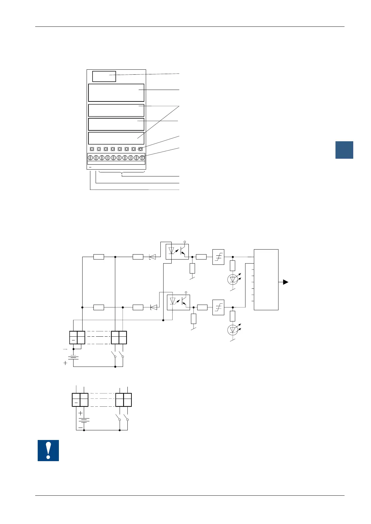
Digital input modules, electrically isolated
LEDs and connection terminals
9 8 7 6 5 4 3 2 1 0
E0E1E2E3E4E5E6E7L
Bus connector
Bus interface and
threshold switch
Input circuits
Electrical isolation by
Optocouplers
LEDs
Screw terminals
Inputs E0 to E7
Input load resistors
User ground (-)
Input circuits and terminal designation
Depending on external wiring, this module may be used for source or sink operation.
Source operation (positive logic):
+5V
E0
E1
6k6
6k6
11k
11k
+5V
E0 E1 L
8 9 0 1
I/O Bus
Ue : 48 VDC
24 VDC
5 VDC
Switch closed
(positive at input) : Input state "H" = LED on
Switch open : Input state "L" = LED off
PCD Bus
Sink operation (negative logic):
E0 E1
1
L
8 9 0
Switch closed
(negative at input) : Input state "H" = LED off
Switch open : Input state "L" = LED on
Ue : 48 VDC
24 VDC
5 VDC
Watchdog: This module can be used on all base addresses; there is no interaction with the
watchdog on the CPUs. For details, please refer to the “Watchdog” section, which describes
the correct use of the watchdog in conjunction with PCD2 components.