Saia-Burgess Controls AG
Manual Manual PCD 1 / PCD 2 Series │ Document 26 / 737 EN22 │ 2013-11-26
5
Input/output (I/O) modules
5-28
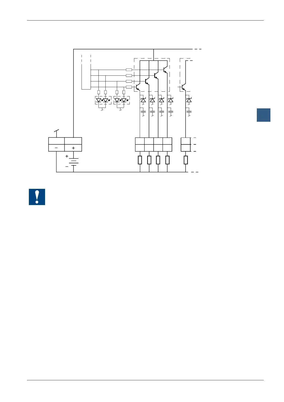
Digital output modules
Output circuits and terminal designation
1, 3, 5, 7
17, 19, 21, 23
9, 11, 13, 15
25, 27, 29, 31
A15 A14
2 4
10 .. 32 VDC
Ribbon cable
connector
6 8
A13 A12
10
A11
8 bit latch
LEDs
Loads
Watchdog: This module can interact with the watchdog; if it is used on base address 240 (or
496 for the PCD2.M17x), the last input with address 255 (or 511 for the PCD2.M17x) cannot
be used.
For details, please refer to the “Watchdog” section, which describes the correct use of the
watchdog in conjunction with PCD2 components.