Saia-Burgess Controls AG
Manual Manual PCD 1 / PCD 2 Series │ Document 26 / 737 EN22 │ 2013-11-26
5
Input/output (I/O) modules
5-30
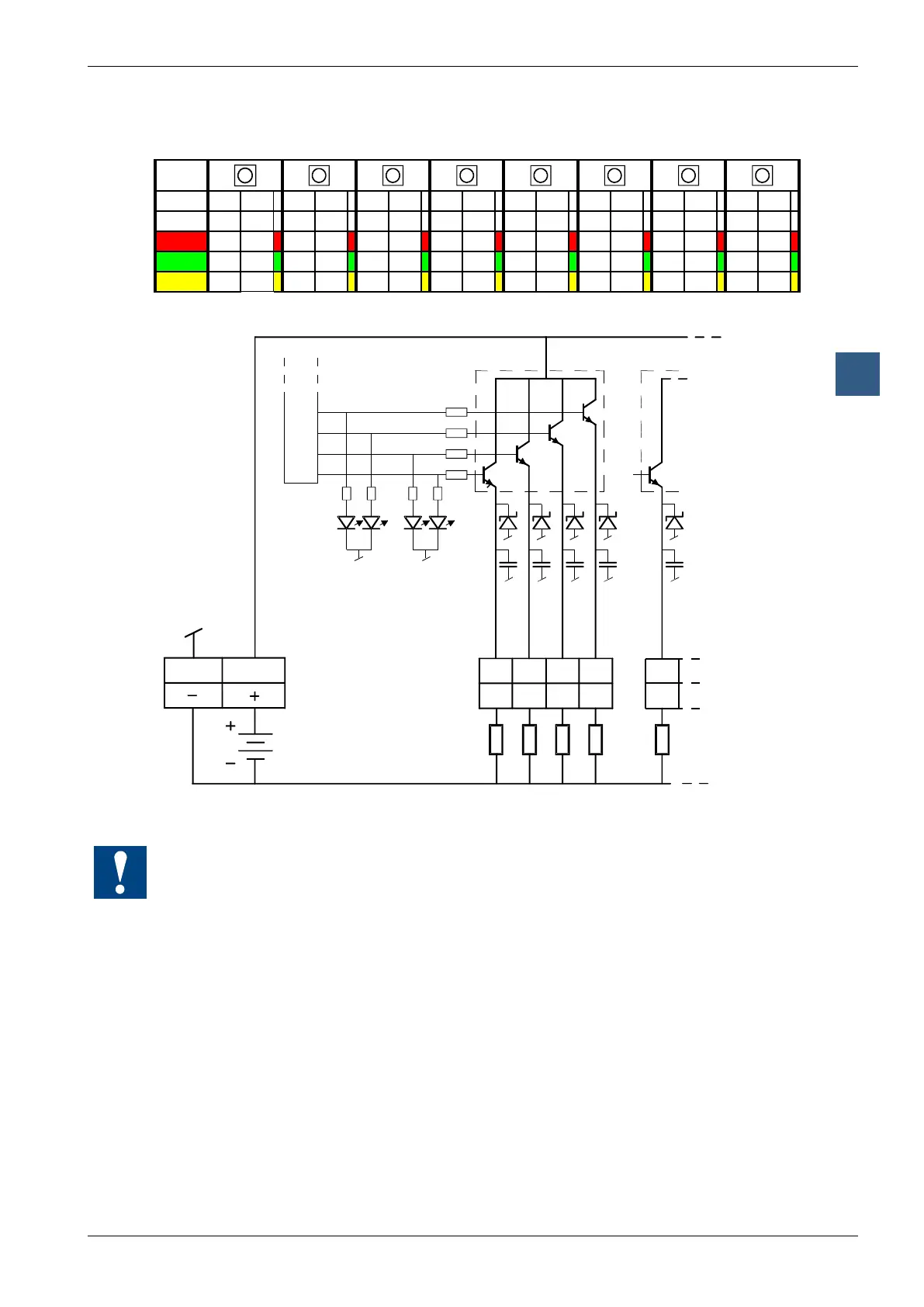
Digital output modules
For every 2 outputs, a 3-colour LED is tted:
LED
A0 A1 A2 A3 A4 A5 A6 A7 A8 A9 A10 A11 A12 A13 A14 A15
off 0 0 0 0 0 0 0 0 0 0 0 0 0 0 0 0
red 1 0 1 0 1 0 1 0 1 0 1 0 1 0 1 0
green 0 1 0 1 0 1 0 1 0 1 0 1 0 1 0 1
yellow 1 1 1 1 1 1 1 1 1 1 1 1 1 1 1 1
Output circuits and terminal designation
Screwless
terminals
Loads
A15 A14
10...32 VDC
A13 A12 A11
8 bit latch
LEDs
18,19 16,17
15 14 13 12
11
Watchdog: This module can interact with the watchdog; if it is used on base address 240 (or
496 for the PCD2.M17x), the last input with address 255 (or 511 for the PCD2.M17x) cannot
be used.
For details, please refer to the “Watchdog” section, which describes the correct use of the
watchdog in conjunction with PCD2 components.