Saia-Burgess Controls AG
Manual Manual PCD 1 / PCD 2 Series │ Document 26 / 737 EN22 │ 2013-11-26
5
Input/output (I/O) modules
5-33
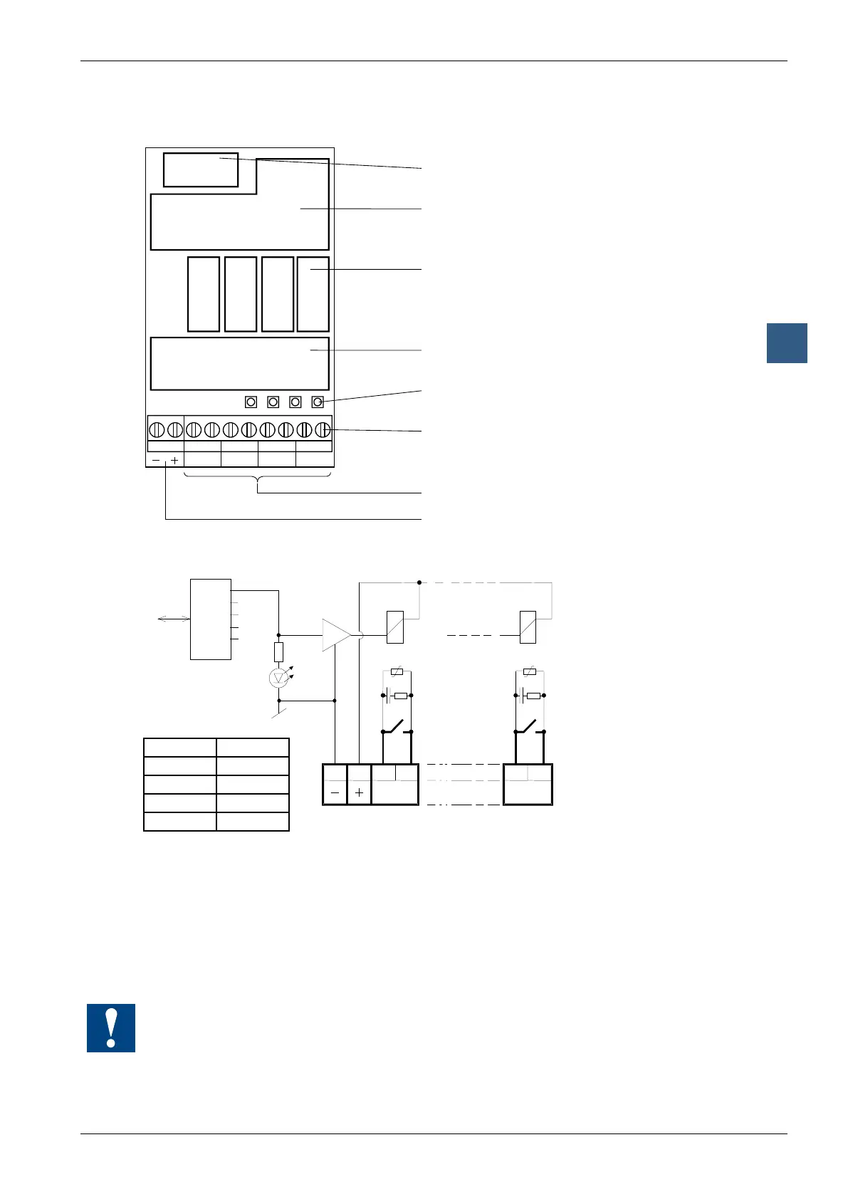
Digital output modules, electrically isolated
LEDs and connection terminals
Bus connector
Bus interface
Relays
Contact protection
LEDs
Screw terminals
Relay contacts
Supply 24 VDC for
Relay coils
9 8 7 6 5 4 3 2 1 0
A0A1A2A3
A0A1A2A3
Output circuits and terminal designation
Contact
protection
Relay
contacts
Terminals
Relay energized (contact closed): LED on
Relay reset (contact open): LED off
24 VDC must be connected to the +/- terminals.
With an open relay contact, the current leakage through the contact protection is
0.7 mA (at 230 V / 50 Hz). This should be taken into account for smaller AC loads.
If this is too high, it is recommended to use a PCD2.A220 Module (without contact
protection).
Watchdog: This module can be used on all base addresses; there is no interaction with the
watchdog on the CPUs. For details, please refer to the “Watchdog” section, which describes
the correct use of the watchdog in conjunction with PCD2 components.
LED Output
0 A0
1 A1
2 A2
3 A3