Saia-Burgess Controls AG
Manual Manual PCD 1 / PCD 2 Series │ Document 26 / 737 EN22 │ 2013-11-26
5
Input/output (I/O) modules
5-39
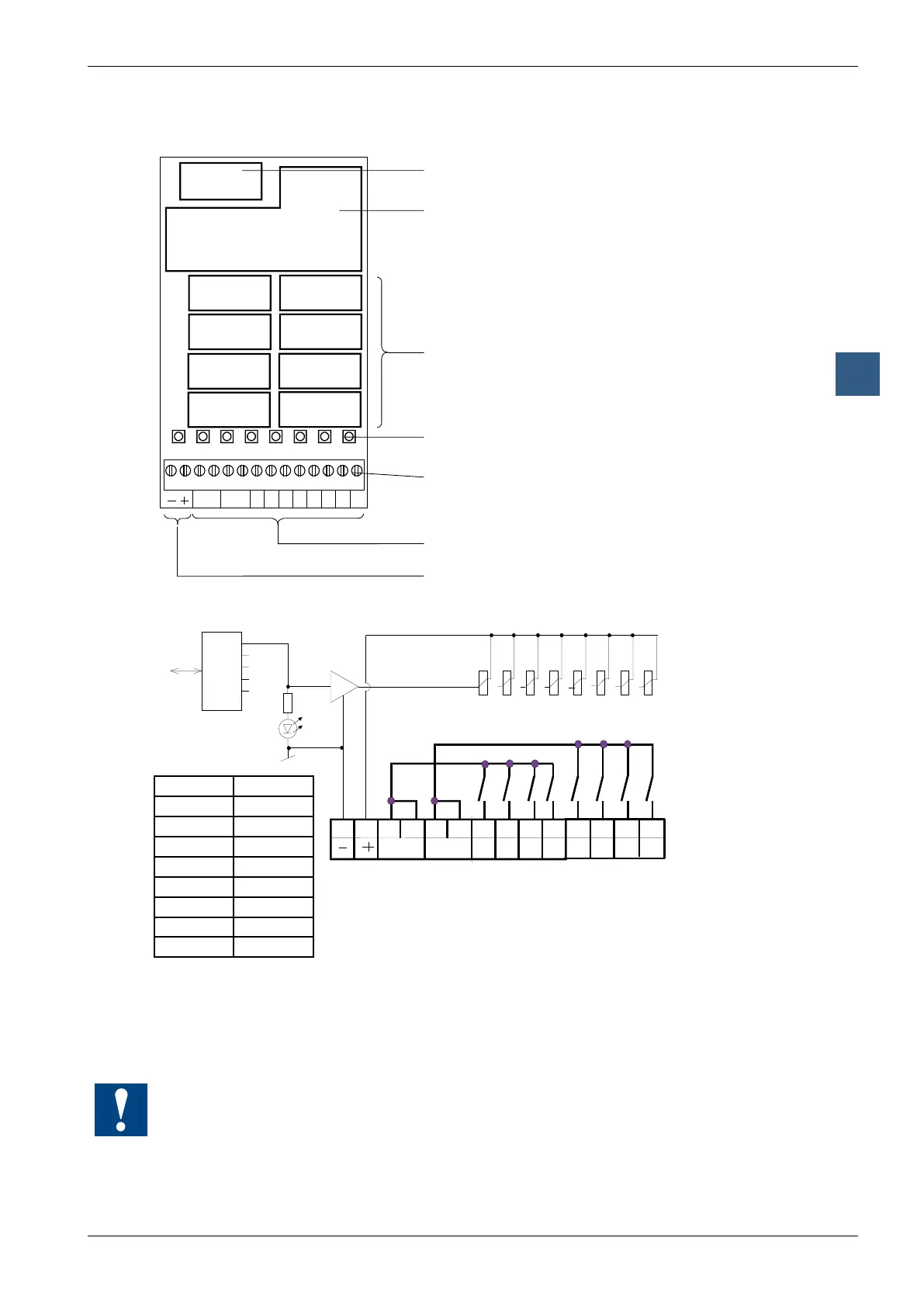
Digital output modules, electrically isolated
LEDs and connection terminals
A0
A1
A3
A4
A5
A7
A2
A6
012345678910111213
A7
A6
A5 A4 A3 A2 A1 A0C4 - 7 C0 - 3
Bus connector
Bus interface
Relay
LEDs
Screw terminals
Relay contacts
Supply 24 VDC for Relay coils
Alimentazione carico 24 VCC
Output circuits and terminal designation
Relay contacts
4 relay contacts have
one common terminal
Address
LED A7
Relay energized (contact closed): LED on
Relay reset (contact open): LED off
24 VDC must be connected to the +/- terminals.
Watchdog: This module can be used on all base addresses; there is no interaction with the
watchdog on the CPUs. For details, please refer to the “Watchdog” section, which describes
the correct use of the watchdog in conjunction with PCD2 components.
LED Outputs
0 A0
1 A1
2 A2
3 A3
4 A4
5 A5
6 A6
7 A7