Saia-Burgess Controls AG
Manual Manual PCD 1 / PCD 2 Series │ Document 26 / 737 EN22 │ 2013-11-26
5
Input/output (I/O) modules
5-45
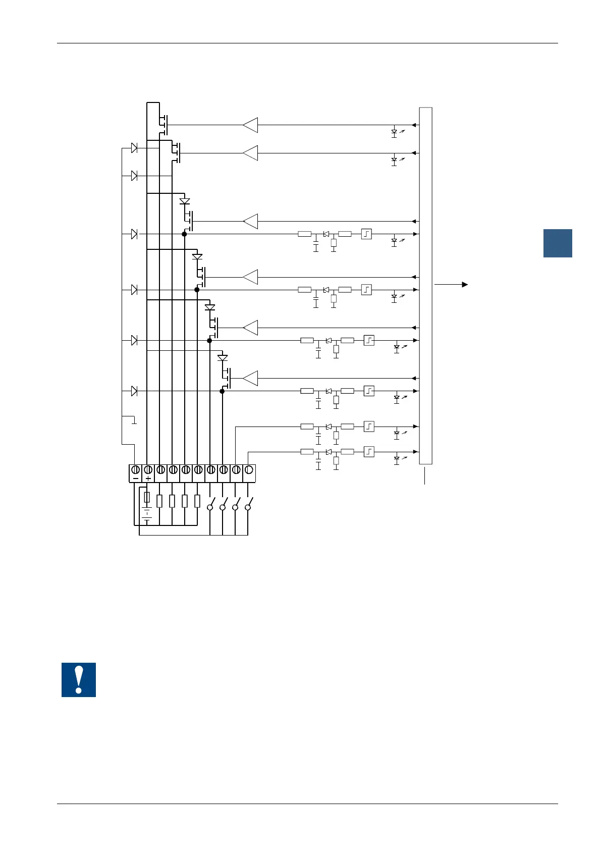
Digital combined input and output modules
Input/output circuits and terminal designation
24 VDC
Fuse
The example shows E/A2 and E/A3 used as inputs and
E/A4 and E/A5 used as outputs
The following applies for the inputs:
Switch closed (input positive): Signal state = “1” = LED on
Switch open: Signal state = “0” = LED off
Fuse: It is recommended that each module should be separately protected with a
fast-blow 3.15 A fuse.
Watchdog: This module can be used on all base addresses; there is no interaction with the
watchdog on the CPUs. For details, please refer to the “Watchdog” section, which describes
the correct use of the watchdog in conjunction with PCD2 components.