Saia-Burgess Controls AG
Manual Manual PCD 1 / PCD 2 Series │ Document 26 / 737 EN22 │ 2013-11-26
5
Input/output (I/O) modules
5-49
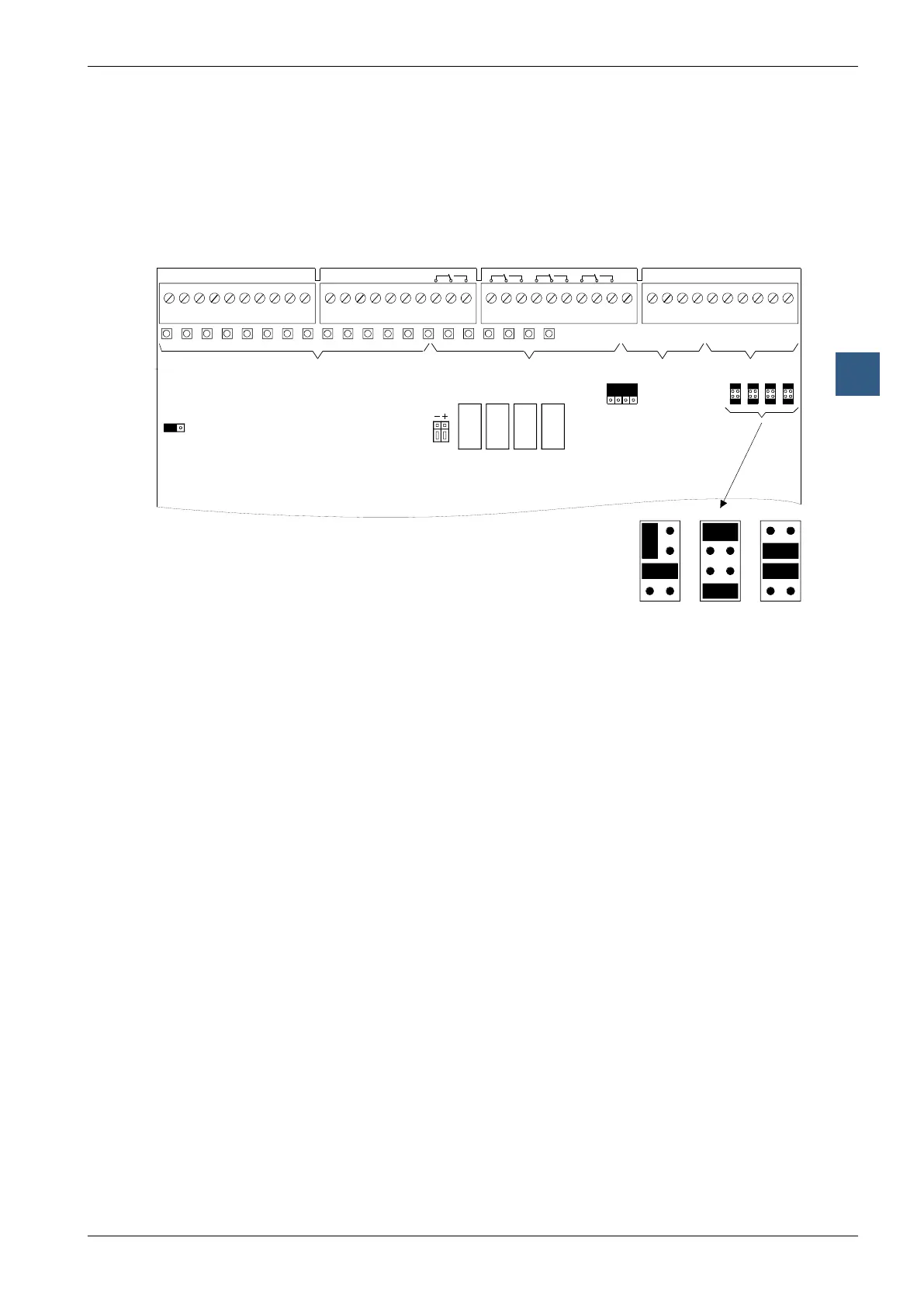
Multi-functional I/O modules
LEDs and connection terminals
The terminal numbering refers to the use of the module on sockets 1 … 4 (top) on
the PCD2. If the module is installed on sockets 5 … 8 (bottom), the value 64 must be
added to the addresses given. When using the module in the PCD2.C100 expansion
housing, the same logic applies, with the value 128 to be added to the ‘top’ and 192
to the ‘bottom’.
A200
Factory settings: E0 … E15 Source operation: Q
A32 … A35 Voltage: 0 … 10 V “U”
E48 … E51 Voltage: 0 … 10 V “U”