Saia-Burgess Controls AG
Manual Manual PCD 1 / PCD 2 Series │ Document 26 / 737 EN22 │ 2013-11-26
5
Input/output (I/O) modules
5-73
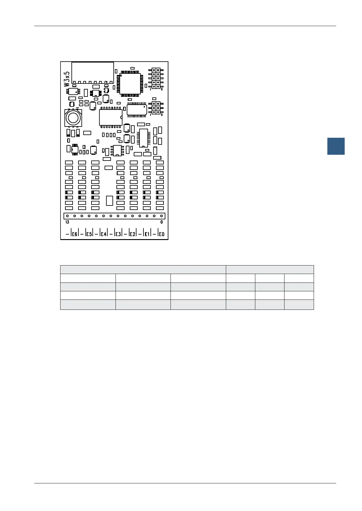
Analogue input modules with electricaly isolation
Terminals
Digital/analogue values
Input signals and type Digital values
PCD2.W305 PCD2.W315 PCD2.W325 Classic xx7 Simatic
+ 10.0 V + 20 mA
+10 V
4095 4095 27684
+ 5.0 V + 10 mA
0 V
2047 2047 13842
0 V 0 mA
-10 V
0 0 0
Connection concept for voltage and current inputs
The voltage and current input signals are connected directly to the 14-pole terminal
block (E0 … E6 and COM). To minimize the amount of interference coupled into the
module via the transmission lines, connection should be made according to the
principle explained below.