Saia-Burgess Controls AG
Manual Manual PCD 1 / PCD 2 Series │ Document 26 / 737 EN22 │ 2013-11-26
5
Input/output (I/O) modules
5-101
Combined analogue I/O modules with galvanic isolation
Signication of the I/O words of a PCD2/3.W525 module?
When conguring a W525 module using the Device Congurator or the Pro-S-I/O
(or Probus DP) Network Congurator, the PCD2/3.W525 does need two registers for
the analogue outputs and 8 registers for the analogue inputs.
The signications of the registers are the following:
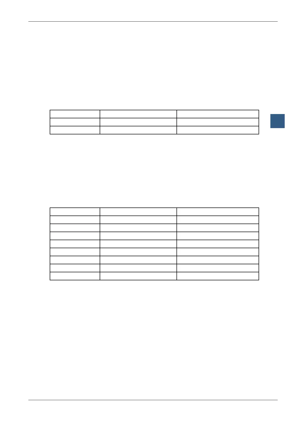
Output registers:
Register Bit 31..16 Bit 15..0
n Value CH0 Output
n+1 Value CH1 Output
Description of the output registers:
Value CH0..1 (Register n, n+1)
This registers (Bit 0 to 15) does contain the analogue output value of the correspond-
ing analogue output. It’s a 12 Bit value.
Input registers:
Register Bit 31..16 Bit 15..0
n Value CH0 Input
n+1 Value CH1 Input
n+2 Value CH2 Input
n+3 Value CH3 Input
n+4 Load Current/Voltage
n+5 Status Module
n+6 Status Input
n+7 Status Output
Description of the input registers:
Value CH0..CH3 (Register n...n+3)
This registers (Bit 0 to 15) does contain the analogue input value of the correspond-
ing analogue input. It’s a 14 Bit value.
Load_Current / Load_Voltage (Register n+4)
On this register (Bit 0 to 15) the actual current or voltage value is displayed.
■ current in [μA] (0..20’000)
■ voltage in [mV] (0..10’000)
 Loading...


