Saia-Burgess Controls AG
Manual Manual PCD 1 / PCD 2 Series │ Document 26 / 737 EN22 │ 2013-11-26
5
Input/output (I/O) modules
5-110
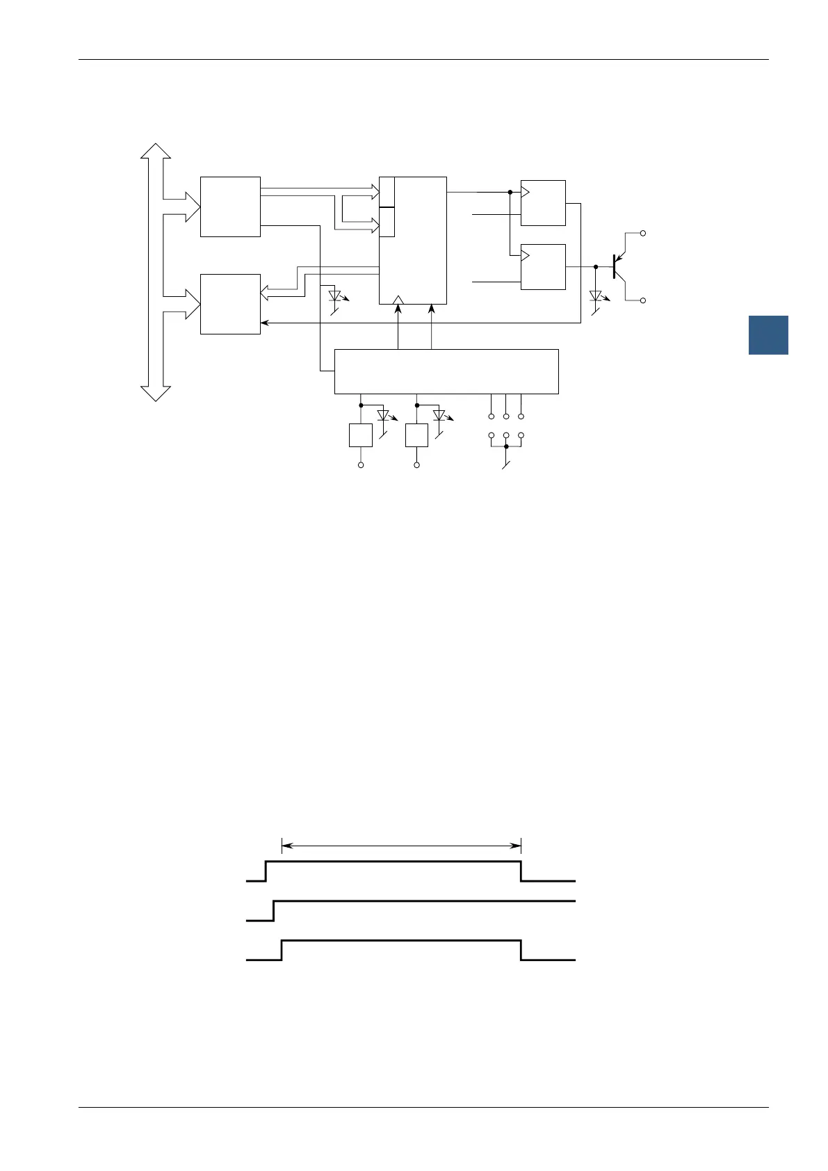
Fast counting modules
Block diagram
SC
x1 x2
Input
Interface
Output
Interface
Counter Flag
Counter enable
Set CCO
PCD BUS
Input
filters
Inputs
Mode
Counter Status Flag
Set
Set CCO
Operating principle
This can be largely derived from the block diagram. It is only necessary to add some
explanation about the counter output circuit:
The output of the internal counter is identied as “Counter Flag”. The user has no
hardware access to it. This counter ag is set to “1” whenever the counter is loaded
or by means of a separate instruction.
The ag is set to “0” in up-counting mode: when counter value 65,535 is
reached
in down-counting mode: when counter value 0 is reached
To reset a CCO hardware output which had previously been set high by the user
program, it is necessary to differentiate between two cases:
a) count range between 0 … 65,535 (normal case)
b) count range exceeding 65,535
Case a): Resetting the counter ag results in a simultaneous reset of the CCO
output.
Counter Flag
Reset Enable
CCO
The “Reset-Enable” should be activated before the counter reaches zero.