Saia-Burgess Controls AG
Manual Manual PCD 1 / PCD 2 Series │ Document 26 / 737 EN22 │ 2013-11-26
CPUs and expansion housings
3-21
Expansion housings and bus cables
3
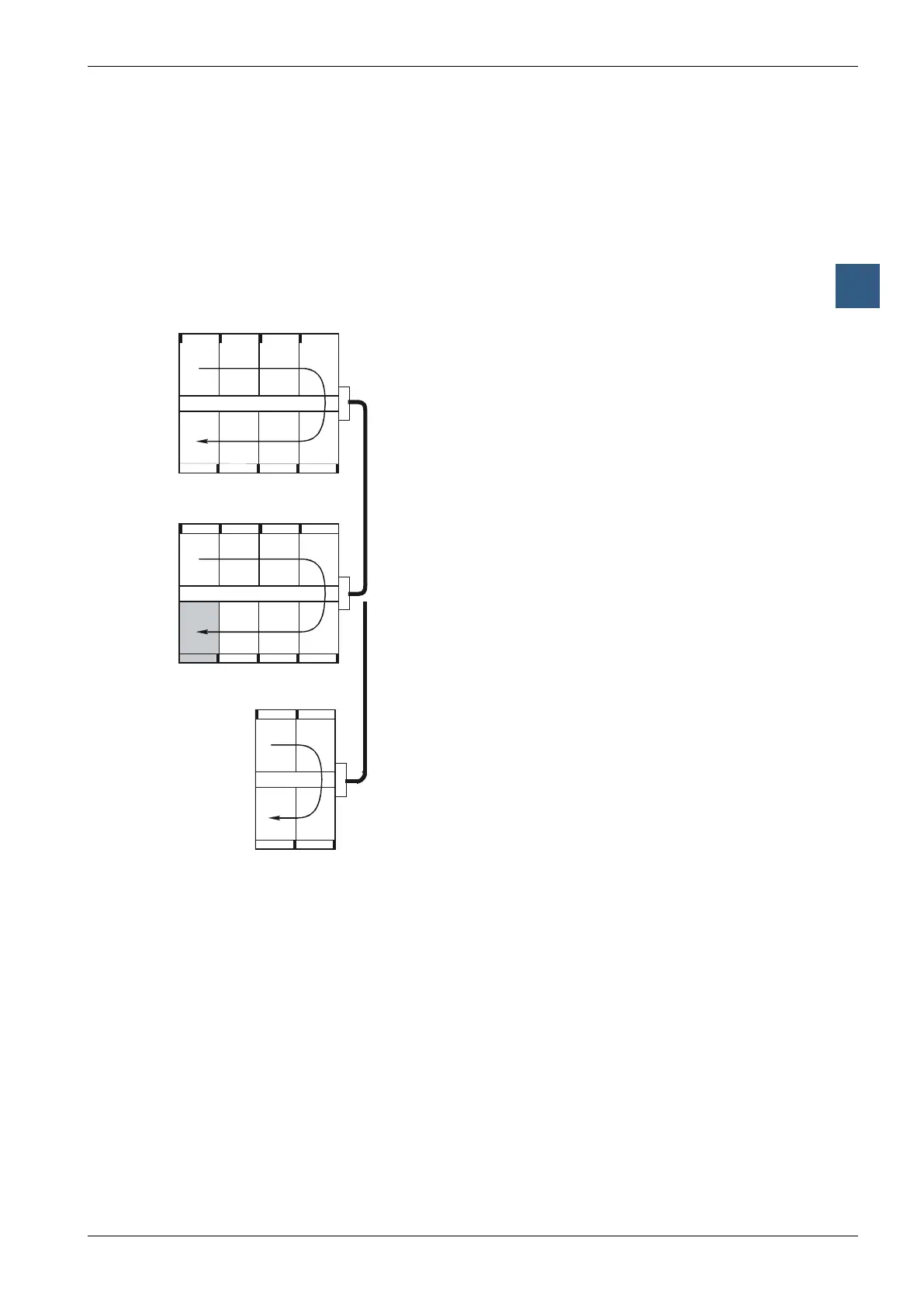
The connection to the base unit is via the 26-core extension cable
● PCD2.K100 formountingbeneatheachother,or
● PCD2.K110 formountingside-by-side
● PCD2.K120 forspecicapplications(length2m)
The PCD2.Mxx0 base units have 8 sockets for input/output modules. The sockets are
numbered clockwise from the top left, from 0 to 7.
The controllers can also be expanded with PCD2.C150 (4-socket) and PCD2.C100
(8-socket) expansion housings to provide up to 15 sockets.
15
14
13
Base unit PCD2.Mxx0
Sockets numbered clockwise from 0 to 7.
AllmodulesoftypesE,A,WandHcanruninany
socket.
The PCD2.T8xx modems cannot be used in all
sockets; please refer to the manual 26/771 for these
modules
PCD2.K100 or K110 bus extension cable
PCD2.C100 expansion housing
Sockets numbered clockwise from 8 to 15.
Socket 15 (shaded) cannot be used for modules of
typesWorH.
PCD2.C150 expansion housing
Sockets numbered clockwise from 8 to 11