Saia-Burgess Controls AG
Manual Manual PCD 1 / PCD 2 Series │ Document 26 / 737 EN22 │ 2013-11-26
CPUs and expansion housings
3-41
Expansion of user memory
3
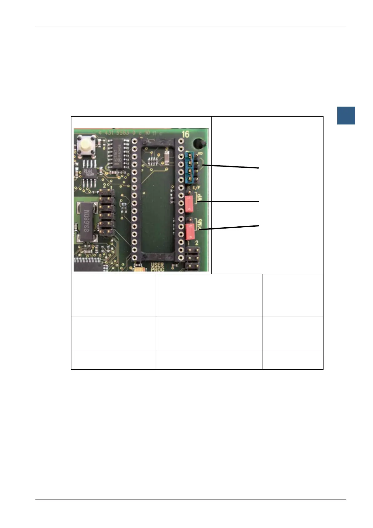
Steps in the correct installation of extended user memory:
1) Switch off power supply and remove the cover of the PCD1
2)Plugtheadditionalmemorychipintothe“USERPROG”socket.
Ensure correct alignment (markings on the socket and the chip must match), and
ensure that all pins on the chip are inserted into the socket
3) Set the jumper next to the socket correctly:
PCD1.M125/M135
Jumper
J1 (Memory type) RAM
EPROM
Flash-EPROM
Position
left; R
1)
right; E/F
right; E/F
2)
J2 (write-protection) Writeprotectionactivated
2)
(only works for RAM and Flash-
EPROM)
Writeprotectiondeactivated
2)
up; WP
1)
down
J4 (memory size <= 1 MBit
or > 1 MBit)
Memory size > 1 MBit
Memory size <= 1 MBit
up
1);
>1MB
down
1) Jumperpositionondelivery:RAM,write-protectiondeactivated,memorysize≤1Mbit
2) Write-protectiononlyaffectsthechipintheUSERPROGsocket
4)ModifythehardwareconfigurationinPG5accordingly,anddownloadthenew
configuration
J1
J2
J4