J-Link / J-Trace (UM08001) © 2004-2017 SEGGER Microcontroller GmbH & Co. KG
35
programming software).
*The actual speed depends on various factors, such as JTAG/SWD, clock speed, host
CPU core etc.
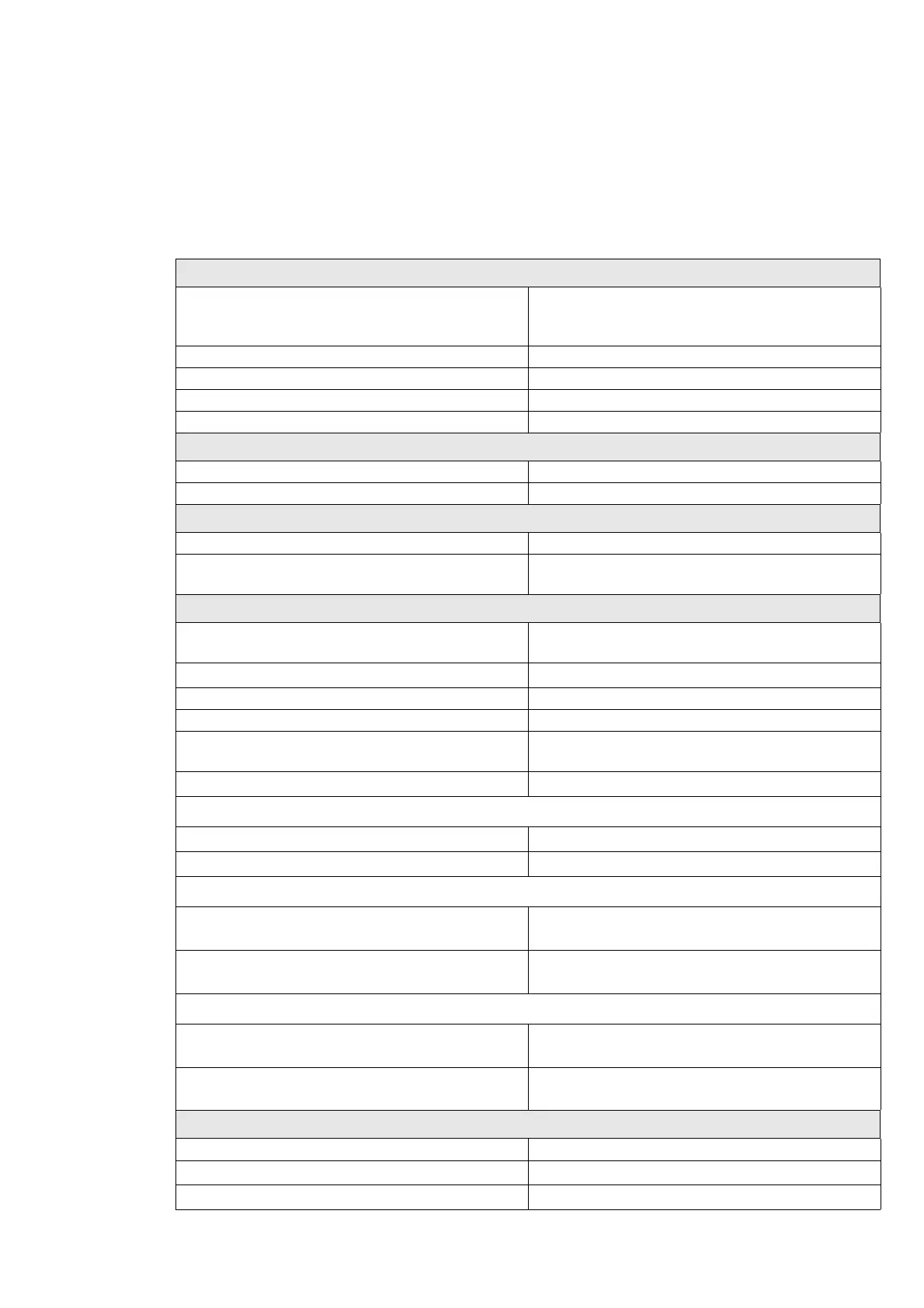
1.3.3.2 Specifications
The following table gives an overview about the specifications (general, mechanical,
electrical) for J-Link PLUS.
General
Supported OS
For a complete list of all operating sys-
tems which are supported, please refer
to Supported OS on page 29.
Electromagnetic compatibility (EMC) EN 55022, EN 55024
Operating temperature +5°C ... +60°C
Storage temperature -20°C ... +65 °C
Relative humidity (non-condensing) Max. 90% rH
Mechanical
Size (without cables) 100mm x 53mm x 27mm
Weight (without cables) 70g
Available interfaces
USB interface USB 2.0, full speed
Target i n t e r f ace
JTAG 20-pin
(14-pin adapter available)
JTAG/SWD Interface, Electrical
Power supply
USB powered
Max. 50mA + Target Supply current.
Target interface voltage (V
IF
)
1.2V ... 5V
Target supply voltage 4.5V ... 5V (if powered with 5V on USB)
Target supply current Max. 300mA
Reset Type
Open drain. Can be pulled low or
tristated.
Reset low level output voltage (V
OL
)V
OL
<= 10% of V
IF
For the whole target voltage range (1.2V <= V
IF
<= 5V)
LOW level input voltage (V
IL
)V
IL
<= 40% of V
IF
HIGH level input voltage (V
IH
)V
IH
>= 60% of V
IF
For 1.8V <= V
IF
<= 3.6V
LOW level output voltage (V
OL
) with a
load of 10 kOhm
V
OL
<= 10% of V
IF
HIGH level output voltage (V
OH
) with a
load of 10 kOhm
V
OH
>= 90% of V
IF
For 3.6 <= V
IF
<= 5V
LOW level output voltage (V
OL
) with a
load of 10 kOhm
V
OL
<= 20% of V
IF
HIGH level output voltage (V
OH
) with a
load of 10 kOhm
V
OH
>= 80% of V
IF
JTAG/SWD Interface, Timing
SWO sampling frequency Max. 7.5 MHz
Data input rise time (T
rdi
)T
rdi
<= 20ns
Data input fall time (T
fdi
)T
fdi
<= 20ns
Table 1.2: J-Link specifications