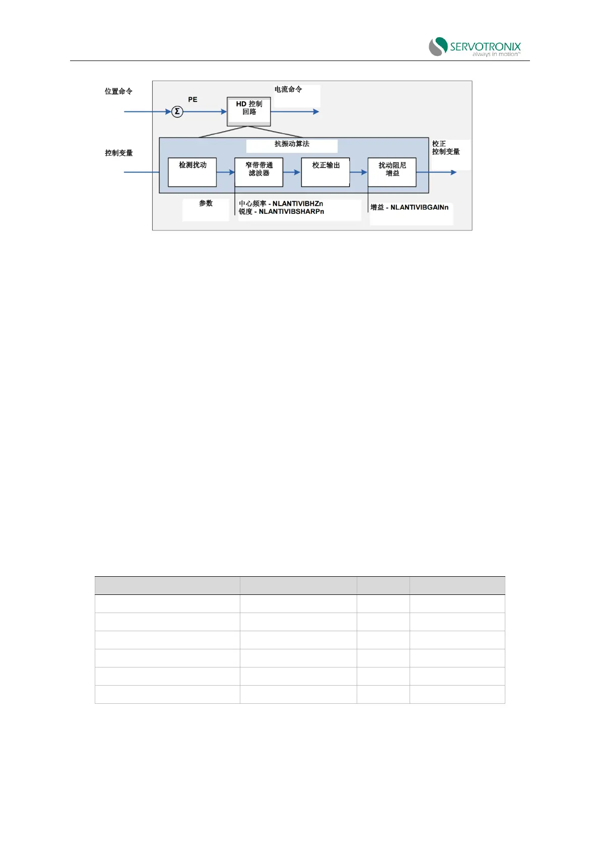
Figure 8-26 Anti-vibration filter
Stage 1: Detect disturbances sensed by the system using various control variables as inputs,
such as position error and current. The disturbed values are calculated for the next stage.
Stage 2: The disturbed values are passed through a narrowband bandpass filter, selecting
disturbances caused by system oscillations. The center frequency and width of the bandpass filter
are set by the parameters NLANTIVIBHZn and NLANTIVIBSHARPn respectively.
Stage 3: Calculate the correction output to be added to the control variable.
Stage 4: Add the correction output to the control variable using the damping gain (parameter
NLANTIVIBGAINn).
Anti-vibration tuning procedure
After autotuning, more anti-vibration tuning may be required.
If additional vibration frequencies need to be suppressed, the tuning process can be repeated
with a second set of anti-vibration filters. The following table shows the parameter values modified
by the tuning procedure.
Table 8-3
Note: Although parameters NLANTIVBHZ, NLANTIVIBSHARP and NLANTIVIBGAIN are still
available, they are not recommended.
1. Set the narrowband center frequency.