Advanced commissioning
6.6 Protection functions
Converter with the CU240B-2 and CU240E-2 Control Units
Operating Instructions, 01/2016, FW V4.7 SP6, A5E34259001B AC
275
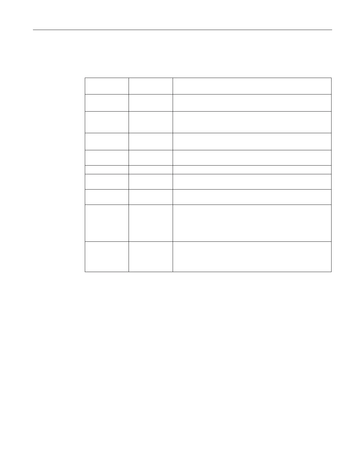
Parameters of the Vdc_max control
The parameters differ depending on the motor control mode.
Parameter for
V/f control
Parameter for
vector control
p1280 = 1 p1240 = 1
Vdc controller configuration
(Factory setting: 1)
1: Vdc controller is enabled
r1282 r1242
Vdc_max control activation level
DC link voltage value above which the Vdc_max control is acti-
p1283 p1243
Vdc_max control dynamic factor
(factory setting: 100 %)
Scaling control parameters p1290, p1291 and p1292
p1284 ---
Vdc_max controller time threshold
Setting the monitoring time of the Vdc_max controller.
Vdc_max control proportional gain (factory setting: 1)
p1291 p1251
Vdc_max control integral time
(factory setting p1291: 40 ms,
p1292 p1252
Vdc_max control rate time
(factory setting p1292: 10 ms, p1252:
p1294 p1254
Vdc_max control automatic ON level sensing
(Factory setting,
dependent on the Power Module)
Automatically sense switch-on levels of the Vdc_max control.
0: Automatic detection disabled
1: Automatic detection enabled
p0210 p0210
If p1254 or p1294 = 0, the inverter uses this parameter to calcu-
late the switch-in thresholds of the Vdc_max control.
Set this parameter to the actual value of the input voltage.
For more information about this function, see the List Manual (function diagrams 6320 and
6220).