Functions, monitoring, and protective functions
9.2 Drive functions
Inverter chassis units
Operating Instructions, 07/2016, A5E00331449A
411
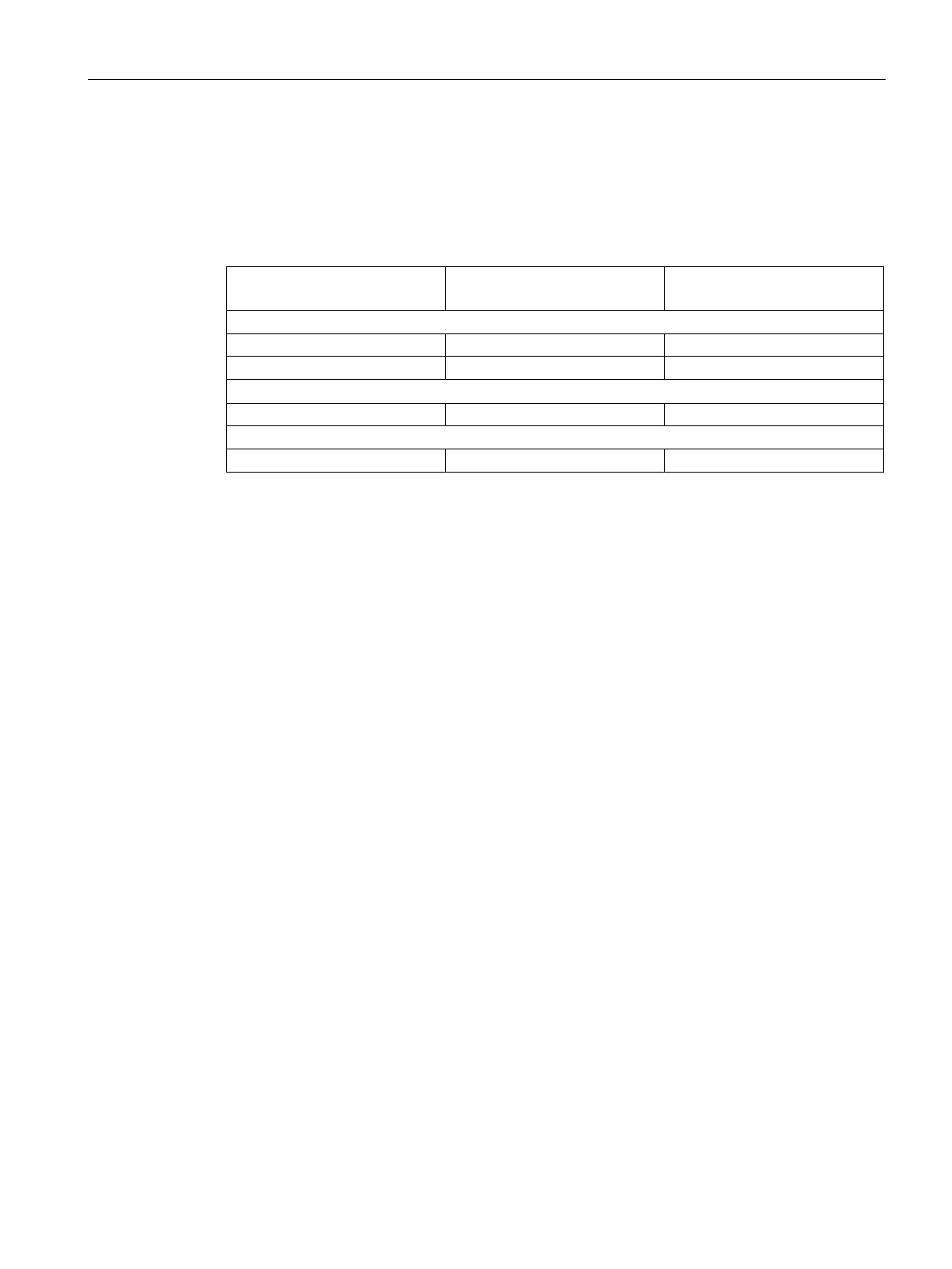
Default pulse frequencies
The specified maximum output frequencies can be achieved with the default pulse
frequencies listed below.
Table 9- 4 Maximum output frequency with default pulse frequency
Default pulse frequency
[kHz]
Maximum output frequency
[Hz]
Line voltage 3 AC 380 ... 480 V
1.25
Line voltage 3 AC 500 ... 600 V
1.25
Line voltage 3 AC 660 ... 690 V
1.25
The pulse frequencies set in the factory are also the minimum frequencies.
The scanning times for the inputs and outputs of the customer terminal block TM31 are set in
the factory to 4000 µs. This is also the minimum limit.
Increasing the pulse frequency
Description
The pulse frequency can be increased in a virtually continuously variable manner to between
the value preassigned in the factory and the maximum pulse frequency which can be set.
1. Parameter p0009 on the Control Unit must be set to 3 "Basic drive configuration".
2. Parameter p0112 "Sampling times default setting p0115" of the DO VECTOR must be set
to 0 "Expert".
3. Use p0113 to enter any pulse frequency between 1 kHz and 2 kHz. If a higher puls
e
f
requency is to be set (e.g., 2.2 kHz), this value must be divided by 2 or by 4 to obtain
a
r
esult between 1 kHz and 2 kHz (e.g., 2.2 kHz divided by 2 is 1.1 kHz).
4. Not all pulse frequencies are accepted in parameter p0113; in such cases, the alar
m
"
Impermissible value" is output.
5. If the frequency entered in parameter p0113 is not accepted, parameter r0114[0]
recommends a different frequency that can deviate from the entered pulse frequency by
several Hertz. This frequency should be entered in p0113.

 Loading...


