Velocities, Setpoint/Actual Value Systems, Closed-Loop Control (G2)
7.3 Setpoint/actual-value system
Turning, Milling, Nibbling
Function Manual, 11/2012, 6FC5397-1CP10-5BA0
127
The following machine data of each machine axis must be parameterized:
● MD30110 CTRLOUT_MODULE_NR[n] Assignment of the drive number
– [n] = 1 (drive number 1) → SP spindle = machine axis 4
– [n] = 2 (drive number 2) → X1 axis = machine axis 1
– [n] = 3 (drive number 3) → Y1 axis = machine axis 2
– [n] = 4 (drive number 4) → Z1 axis = machine axis 3
– [n] = 5 (drive number 5) → A1 axis = machine axis 5
● MD30130 CTRLOUT_TYPE[n] Setpoint output type. The speed setpoint output type is
entered here
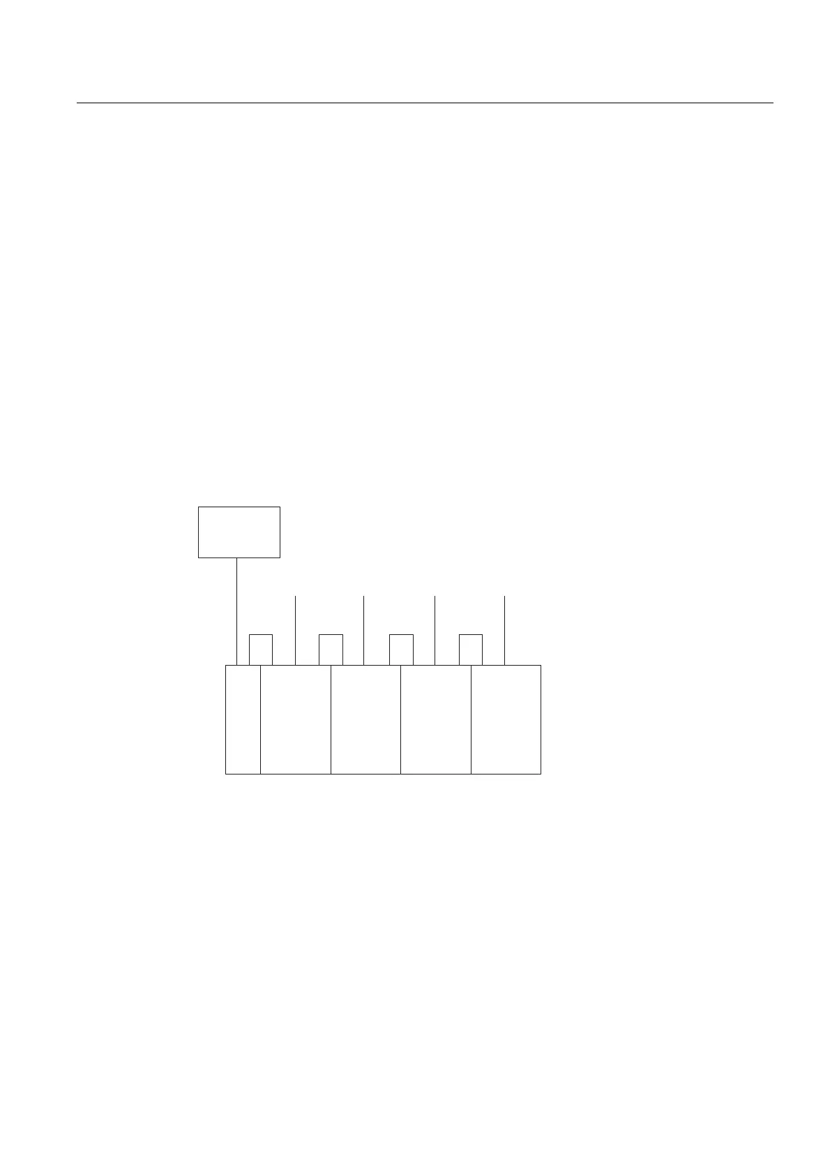
Actual-value routing
Due to the fixed assignment of the encoder (measuring system) to the drive, the actual value
assignment must be performed identically to the speed setpoint assignment (the same drive
number). For the actual-value assignment, please refer to the diagram below. The
parameterization is described in the associated machine data:
=
0RWRU
0RGXOH
<
0RWRU
0RGXOH
'5,9(&/L4PHDVXULQJV\VWHP
6,1$0,&6
;
;
0RWRU
0RGXOH
$/0
6SLQGOH
0RWRU
0RGXOH
'VO
'ULYH'ULYH'ULYH'ULYH
;
;
;
;
;
;
;
;
;
;
;
;
;
'5,9(&/L4PHDVXULQJV\VWHP
'5,9(&/L4PHDVXULQJV\VWHP
'5,9(&/L4PHDVXULQJV\VWHP
Figure 7-4 Actual-value assignment, example
The following machine data of each machine axis must be parameterized:
● MD30220 ENC_MODULE_NR[n] Assignment of the drive number
– [n] = 1 (drive number 1) → SP spindle = machine axis 4
– [n] = 2 (drive number 2) → X1 axis = machine axis 1
– [n] = 3 (drive number 3) → Y1 axis = machine axis 2
– [n] = 4 (drive number 4) → Z1 axis = machine axis 3
– [n] = 5 (drive number 5) → A1 axis = machine axis 5
● MD30240 ENC_TYPE[n] Type of actual-value assignment; enter the encoder type you
are using here.

 Loading...


