Spindle (S1)
20.8 Analog spindle
Turning, Milling, Nibbling
Function Manual, 11/2012, 6FC5397-1CP10-5BA0
365
20.8 Analog spindle
Function
With the "Analog spindle" function, the MCPA option module is used as the setpoint output,
and a free DRIVE-CLiQ encoder interface is used as the actual-value input.
For more detailed information see the "adi4.ini" file, which is part of the toolbox and can be
found in the "...\Toolbox 802D_sl\V01040000\Special\ADI4" directory.
For the analog spindle without encoder, MD30240 ENC_TYPE[n] must be set to zero.
20.9 Data lists
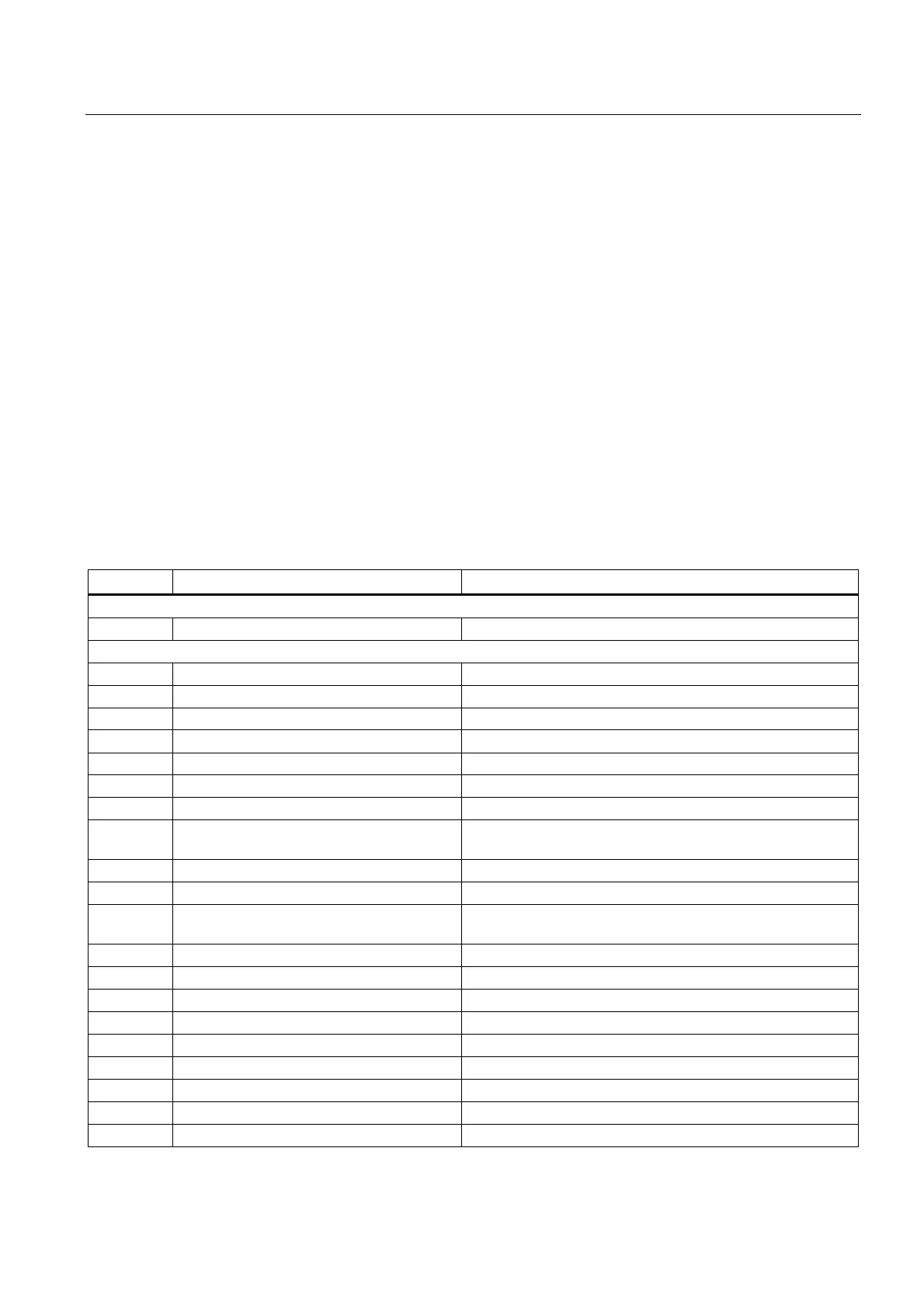
20.9.1 Machine data
Number Identifier Name
Channel-specific
20090 SPIND_DEF_MASTER_SPIND Master spindle
Axis-specific
30134 IS_UNIPOLAR_OUTPUT[0] Setpoint output is unipolar
30300 IS_ROT_AX Rotary axis
30310 ROT_IS_MODULO Modulo conversion
30320 DISPLAY_IS_MODULO Position display
31050 * DRIVE_AX_RATIO_DENOM[n] Denominator load gearbox
31060 * DRIVE_AX_RATIO_NUMERA[n] Numerator load gearbox
32200 * POSCTRL_GAIN [n] Servo gain factor Kv
32810 * EQUIV_SPEEDCTRL_TIME [n] Equivalent time constant speed control circuit for feedforward
control
34040 REFP_VELO_SEARCH_MARKER Reference point creep speed
34060 REFP_MAX_MARKER_DIST Monitoring of zero mark distance
34080 REFP_MOVE_DIST Reference point distance/destination point for distancecoded
system
34090 REFP_MOVE_DIST_CORR Reference point offset/absolute offset, distancecoded
34100 REFP_SET_POS Reference point value
34200 ENC_REFP_MODE Referencing mode
35000 SPIND_ASSIGN_TO_MACHAX Assignment of spindle to machine axis
35010 GEAR_STEP_CHANGE_ENABLE Gear stage change possible
35040 SPIND_ACTIVE_AFTER_RESET Spindle active after reset
35100 SPIND_VELO_LIMIT Maximum spindle speed
35110 * GEAR_STEP_MAX_VELO[n] Maximum speed for gear change
35120 * GEAR_STEP_MIN_VELO[n] Minimum speed for gear change

 Loading...


