Commissioning Manual
6FC5397-4EP10-0BA8, 07/2018
141
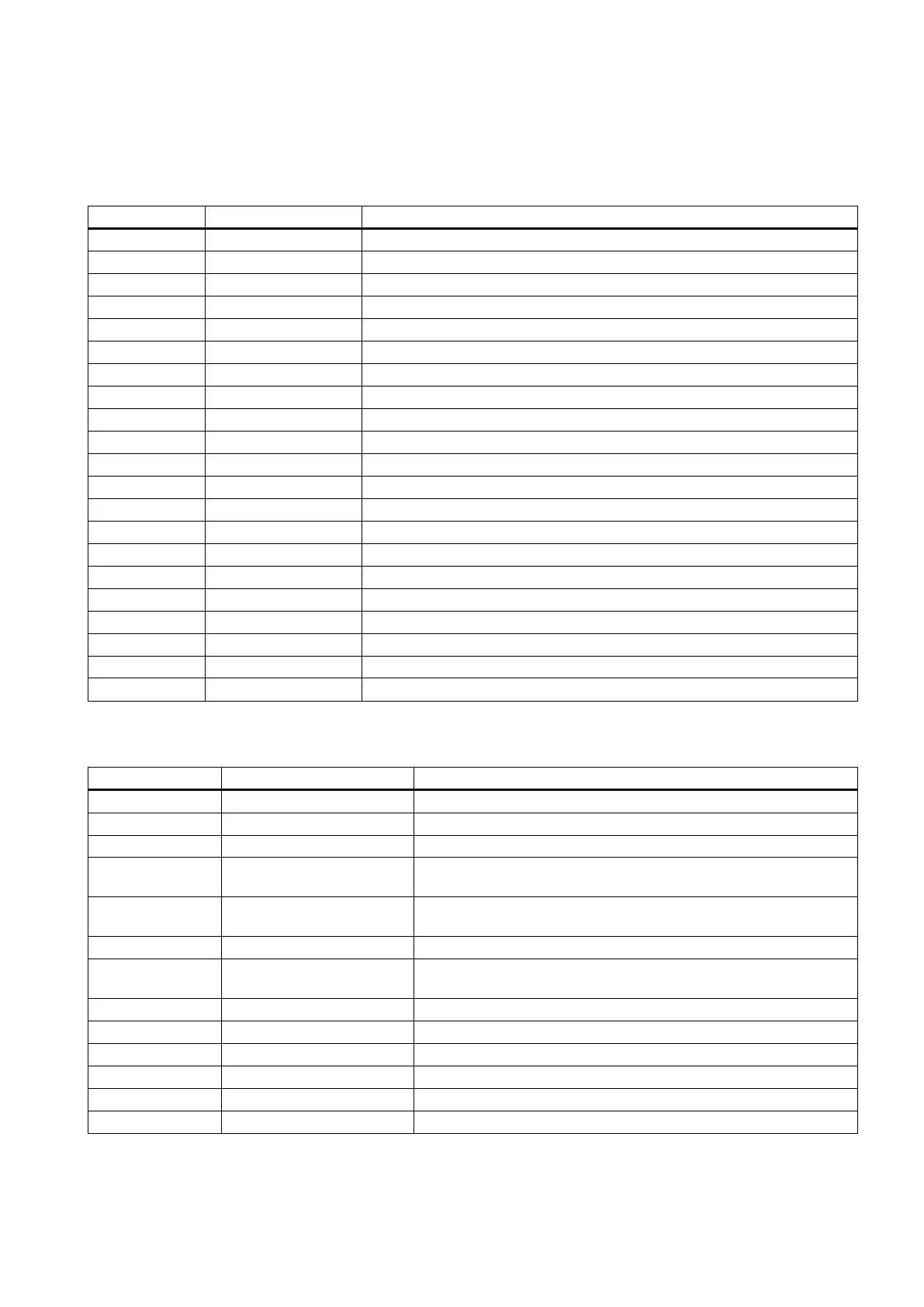
Structure of symbol tables
All the addresses in the PLC subroutine library are programmed with symbols. All the signals of interfaces are named by
symbols and arranged in different symbol tables.
The name of a symbol follows some conventions. For details, see Section "Conventions for the symbols used in the
subroutines (Page 143)".
Module I/O are defined by the manufacturer
Distributed I/O are defined by the manufacturer
Reserved for the manufacturer
PLC selects part programs
Auxiliary functions from the NCK
Signals from/to the channel
21 IS_AX1 Signals to/from axis 1
Global memory used in the sample applications and subroutines
Reserved for the sample applications and subroutines
PLC sample subroutines offer PLC functions for the machine tool.
Working lamp control, called in the subroutine "AUX_MCP"
22 AUX_SAFE_DOOR Safety door control, called in the subroutine "AUX_MCP" for a milling
23 AUX_CHIP Chip conveyor control, called in the subroutine "AUX_MCP" for a
Three-color lamp control, called in the subroutine "AUX_MCP"
31 PLC_ini_USR_INI Reserved for initialization functions of the manufacturer (this subrou-
tine is automatically called by subroutine 32)
PLC initialization, executed at the first PLC cycle (SM0.1)
Signals from the MCP and HMI are sent to NCK interfaces
38 MCP_Tool_Nr Display tool numbers via the 7-segment LED of the MCP
Handwheel selection via the HMI
40 AXIS_CTL Control of feed axis enable and spindle enable

 Loading...


