Commissioning Manual
152 6FC5397-4EP10-0BA8, 07/2018
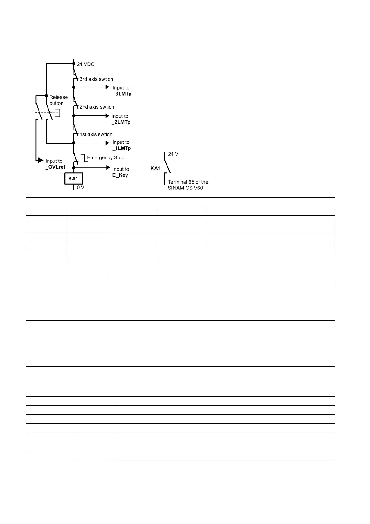
● Hardware solution (MD14512 [18] bit 6 = 1)
This solution is independent of the PLC and thus is much safer:
Encoding the hardware limit switches
0 1 1 1 - EMERGENCY STOP
active
0 0 1 1 DB3900.DBX4.6 1st - over limit
In the hardware solution above, the feed stop signals for all axes can be activated via the hardware limit switches when any
of the hardware limits is reached or an EMERGENCY STOP happens. You can check the information of the PLC diagnostics
from the encoding of the hardware limit switches shown in the table above, and identify the cause (Emergency Stop button
or a hardware limit switch of an axis) of the EMERGENCY STOP signal.
Note
When using the hardware solution, you must take below information into consideration:
You must assign the axes on
e by one; for example, X axis, Z axis, spindle or X axis, Y axis, Z axis, spindle. You must not
assign the axes like X axis, Y axis, spindle, Z axis.
You must set constant "1" (i.e. SM0.0) to the input signals of the hardware limits for undefined axes; otherwise, the
hardware limits of the undefined axes can be activated.
Local variable definition
Inputs
NC being in the cyclic state and able to enable the drive
Positive hardware limit switch of 1st axis (NC)
1)
Negative hardware limit switch of 1st axis (NC)
Reference cam of 1st axis (NO)
Positive hardware limit switch of 2nd axis (NC)
1)

 Loading...


