Commissioning Manual
6FC5397-4EP10-0BA8, 07/2018
153
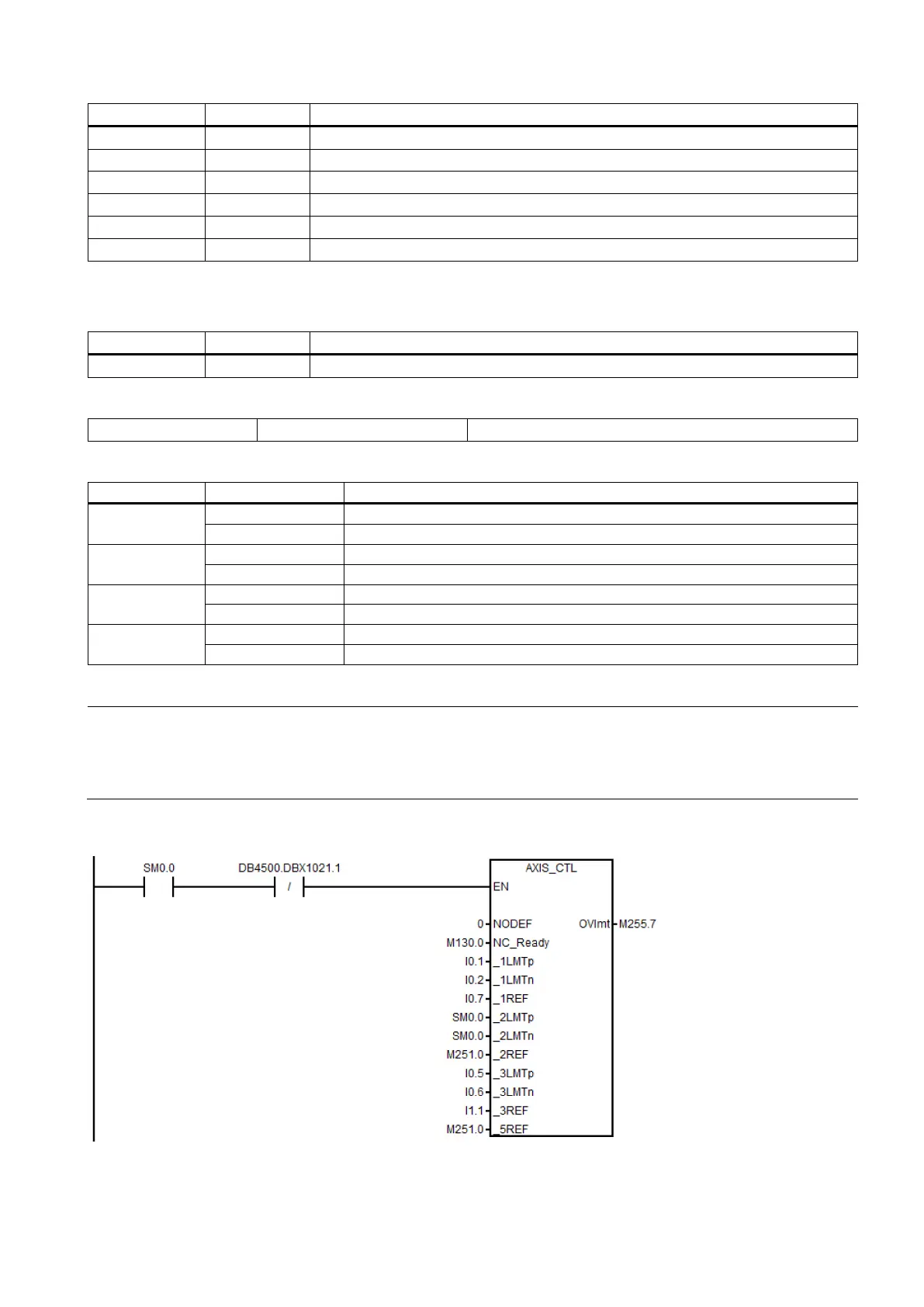
Negative hardware limit switch of 2nd axis (NC)
Reference cam of 2nd axis (NO)
Positive hardware limit switch of 3rd axis (NC)
1)
Negative hardware limit switch of 3rd axis (NC)
Reference cam of 3rd axis (NO)
Reference Cam of 5th axis (NO)
1)
The hardware limit + is used for the input if there is only one hardware limit switch or when the hardware solution is
used.
Any of the axis over hardware limits
Assigned global variables
Spindle start command (CW or CCW)
Relevant PLC machine data
Overtravel employs the hardware solution
Overtravel employs the PLC solution
Each axis has only one hardware limit switch
Each axis direction has an hardware limit switch
Disable by pressing the spindle stop key
Disable when detecting the standstill speed
1)
Set I0.0 to I2.7/Q0.0 to Q1.7 as the standard I/O wiring in the default PLC
Set I6.0 to I8.7/Q4.0 to Q5.7 as the standard I/O wiring in the default PLC
1)
When setting bit 1 to 1, make sure that the speed control mode is active.
Note
By default, the value of MD30350 is 0
, indicating that the NC will run in the real axis mode. When performing th
e axis control
related operations on a stand
-alone controller without any connection to the motor or drive, you need to set MD30350 to
for each axis, which indicates that the axis will run in the simulated state and thus the PLC will not detect the drive
ready
signal; otherwise, an alarm will be thrown out, indicating axis enable missing.
Example for calling subroutine 40

 Loading...


