Nominal current
Ι
Nom Motor
= 545 A
Continuously permissible negative
sequence current
Ι
2 dd prim
/Ι
Nom Motor
= 0.11 continuous
Briefly permissible negative
sequence current
Ι
2 long-term prim
/Ι
Nom Motor
= 0.55 for Tmax = 1 s
Current transformer
Ι
Nom prim
/Ι
Nom sec
= 600 A/1 A
Setting value 46-1 Pickup = 0.11 · 545 A · (1/600 A) = 0.10 A
Setting value 46-2 Pickup = 0,55 · 545 A · (1/600 A) = 0,50 A
When protecting feeder or cable systems, unbalanced load protection may serve to identify low magnitude
unsymmetrical faults below the pickup values of the directional and non-directional overcurrent elements.
Here, the following must be observed:
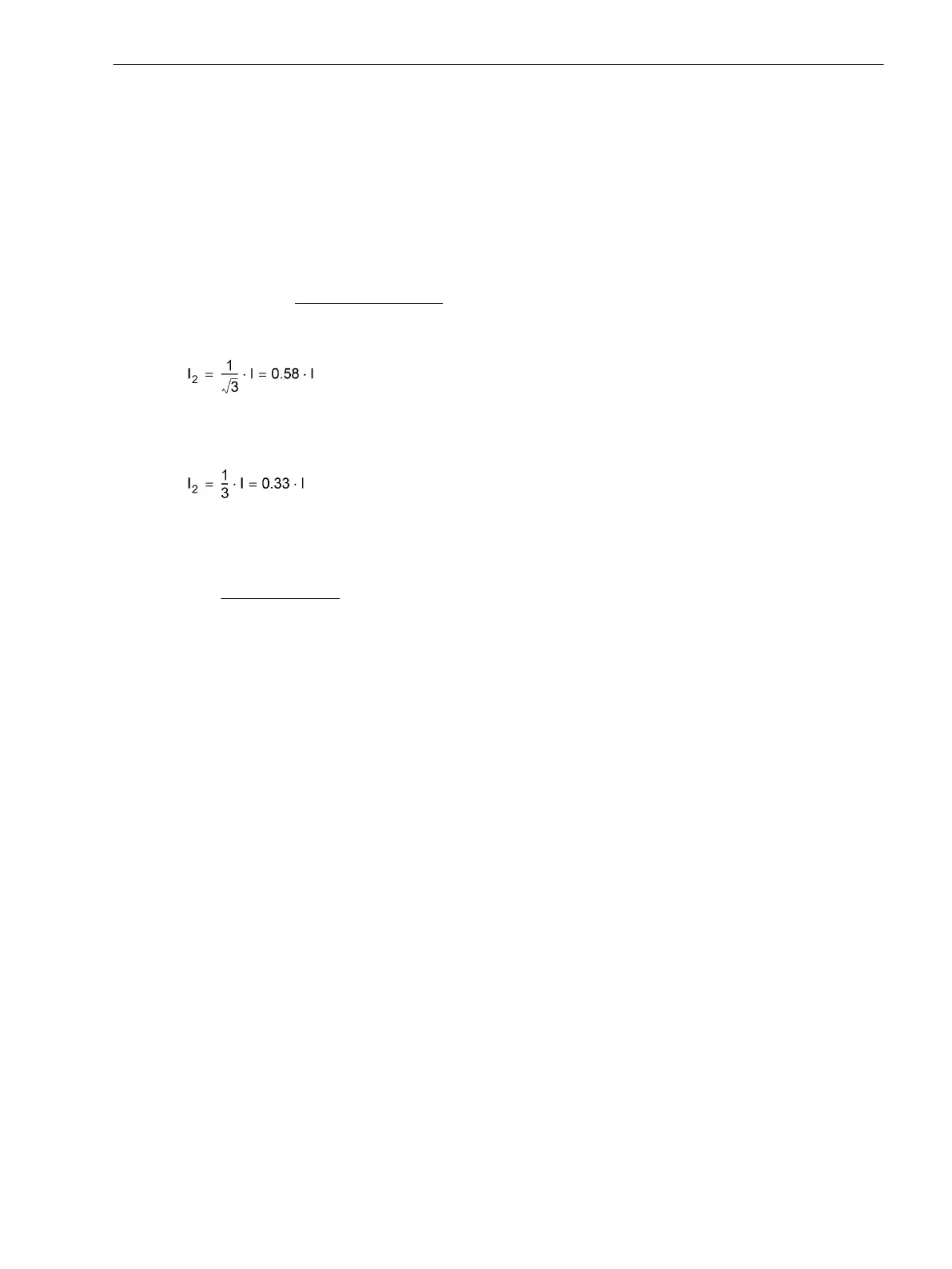
[formel-i2-058-260602-kn, 1, en_US]
A phase-to-ground fault with current
Ι corresponds to the following negative sequence current:
[formel-i2-033-260602-kn, 1, en_US]
On the other hand, with more than 60% of unbalanced load, a phase-to-phase fault can be assumed. The
delay time 46-2 DELAY must be coordinated with the system grading of phase-to-phase faults.
For a power transformer, unbalanced load protection may be used as sensitive protection for low magnitude
phase-to-ground and phase-to-phase faults. In particular, this application is well suited for delta-wye trans-
formers where low side phase-to-ground faults do not generate high side zero sequence currents (e.g. vector
group Dy).
Since transformers transform symmetrical currents according to the transformation ratio "CTR", the relation-
ship between negative sequence currents and total fault current for phase-to-phase faults and phase-to-
ground faults are valid for the transformer as long as the turns ratio "CTR" is taken into consideration.
Consider a transformer with the following data:
Base Transformer Rating
S
NomT
= 16 MVA
Primary Nominal Voltage V
Nom
= 110 kV
(TR
V
= 110/20)
Secondary Nominal Voltage V
Nom
= 20 kV
Vector Groups Dy5
High Side CT 100 A/1 A (CT
Ι
= 100)
The following fault currents may be detected at the low side:
If 46-1 PICKUP on the high side of the devices is set to = 0.1, then a fault current of Ι = 3 · TR
V
· TR
Ι
· 46-1
PICKUP = 3 · 110/20 · 100 · 0.1 A = 165 A for single-phase faults and √3 · TR
V
· TR
Ι
· 46-1 PICKUP = 95 A can
be detected for two-phase faults at the low side. This corresponds to 36% and 20% of the transformer nominal
current respectively. It is important to note that load current is not taken into account in this simplified
example.
As it cannot be recognized reliably on which side the thus detected fault is located, the delay time 46-1
DELAY must be coordinated with other downstream relays in the system.
Pickup Stabilization (definite-time overcurrent protection)
Pickup of the definite time elements can be stabilized by means of a configurable dropout time. This dropout
time is set in 4012 46 T DROP-OUT.
Functions
2.7 Negative Sequence Protection 46
SIPROTEC 4, 7SJ62/64, Manual 141
C53000-G1140-C207-8, Edition 08.2016

 Loading...


