Home
Siemens
Protection Device
SIPROTEC 4
Siemens SIPROTEC 4 User Manual
5
of 1
of 1 rating
734 pages
Give review
Manual
Specs
To Next Page
To Next Page
To Previous Page
To Previous Page
Loading...
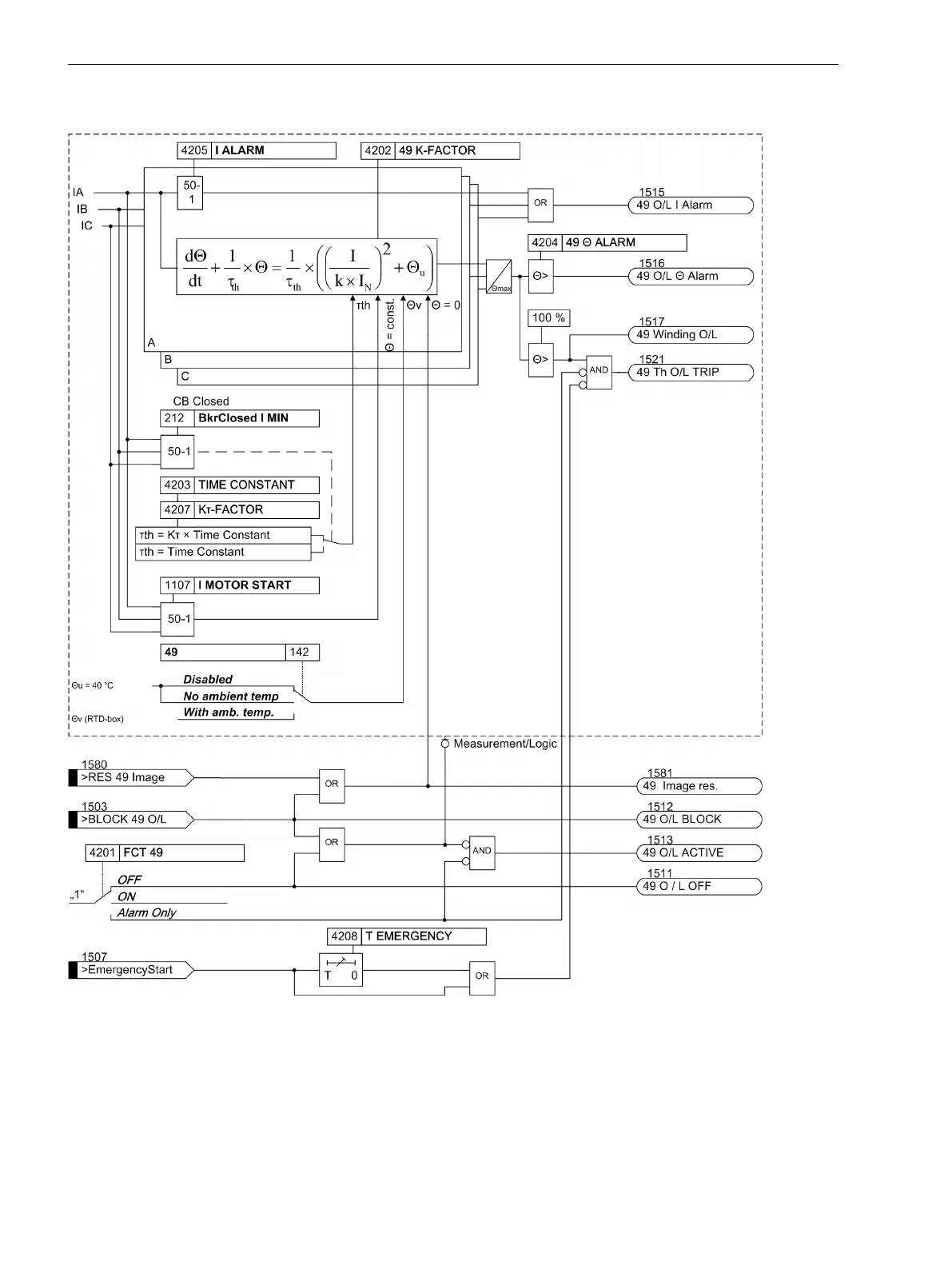
The following figure shows the logic diagram for the overload protection function.
[7sj6x_ueberlastschutz-150502-kn, 1, en_US]
Figure 2-68
Logic diagram of the overload protection
Functions
2.11 Thermal Overload Protection 49
174
SIPROTEC 4, 7SJ62/64, Manual
C53000-G1140-C207-8, Edition 08.2016
173
175
Table of Contents
Default Chapter
3
Preface
3
Table of Contents
9
1 Introduction
19
Overall Operation
20
Application Scope
23
Characteristics
25
2 Functions
31
General
32
Functional Scope
32
Description
32
Setting Notes
32
Settings
34
Device, General Settings
36
Command-Dependent Messages
37
Setting Notes
38
Settings
38
Information List
39
Power System Data 1
40
Description
40
Setting Notes
41
Settings
46
Information List
48
Oscillographic Fault Records
48
Description
48
Setting Notes
49
Settings
49
Information List
50
Settings Groups
50
Description
50
Setting Notes
50
Settings
50
Information List
51
Power System Data 2
51
Description
51
Setting Notes
51
Settings
54
Information List
55
EN100-Module
56
Description
56
Setting Notes
56
Information List
56
Overcurrent Protection 50, 51, 50N, 51N
57
General
57
Definite Time, High-Set Elements 50-3, 50-2, 50N-3, 50N-2
58
Definite Time Overcurrent Elements 50-1, 50N-1
60
Inverse Time Overcurrent Elements 51, 51N
63
Inverse Time Overcurrent Protection 51V (Voltage-Controlled / Voltagerestraint)
66
Dynamic Cold Load Pickup Function
68
Inrush Restraint
69
Pickup Logic and Tripping Logic
70
Two-Phase Overcurrent Protection (Only Non-Directional)
71
Fast Busbar Protection Using Reverse Interlocking
72
Setting Notes
73
Settings
80
Information List
83
Directional Overcurrent Protection 67, 67N
85
General
85
Definite Time Directional High-Set Elements 67-2, 67N-2, 67-3, 67N-3
87
Definite Time, Directional Time Overcurrent Elements 67-1, 67N-1
88
Inverse Time, Directional Time Overcurrent Elements 67-TOC, 67N-TOC
91
Interaction with Fuse Failure Monitor (FFM)
92
Dynamic Cold Load Pickup Function
93
Inrush Restraint
93
Determination of Direction
93
Reverse Interlocking for Double End Fed Lines
97
Setting Notes
98
Settings
106
Information List
109
Dynamic Cold Load Pickup
111
Description
111
Setting Notes
113
Settings
114
Information List
116
Single-Phase Overcurrent Protection
117
Description
117
High-Impedance Ground Fault Unit Protection
118
Tank Leakage Protection
120
Setting Notes
121
Settings
126
Information List
126
Voltage Protection 27, 59
127
Measurement Principle
127
Overvoltage Protection 59
128
Undervoltage Protection 27
129
Setting Notes
132
Settings
135
Information List
136
Negative Sequence Protection 46
137
Definite Time Characteristic
137
Inverse Time Characteristic 46-TOC
138
Setting Notes
140
Settings
142
Information List
143
Motor Protection
144
Motor Starting Protection 48
144
Description
144
Setting Notes
147
Motor Restart Inhibit 66
148
Description
149
Setting Notes
153
Load Jam Protection (51M)
157
Description
157
Setting Notes
159
Motorprotection (Motor Starting Protection 48, Motor Restart Inhibit 66, Loadjam)
161
Settings
161
Information List
162
Frequency Protection 81 O/U
163
Description
163
Setting Notes
164
Settings
165
Information List
166
Functional Description
167
Setting Notes
169
Settings
170
Information List
171
Thermal Overload Protection 49
172
Description
172
Setting Notes
175
Settings
178
Information List
179
Monitoring Functions
180
Measurement Supervision
180
General
180
Hardware Monitoring
180
Monitoring of the Hardware Modules
182
Software Monitoring
183
Monitoring of the Transformer Circuits
183
Measurement Voltage Failure Detection
185
Broken Wire Monitoring of Voltage Transformer Circuits
189
Setting Notes
190
Settings
191
Information List
192
Trip Circuit Supervision 74TC
193
Description
193
Setting Notes
196
Settings
196
Information List
197
Malfunction Responses of the Monitoring Functions
197
Description
197
Ground Fault Protection 64, 67N(S), 50N(S), 51N(S)
200
Ground Fault Detection for Cos-Φ / Sin-Φ Measurement (Standard Method)
200
Ground Fault Detection for V0/I0-Φ Measurement
206
Ground Fault Location
211
Setting Notes
212
Settings
221
Information List
223
Intermittent Ground Fault Protection
225
Description
225
Setting Notes
228
Settings
229
Information List
230
Dir. Intermittent Earth Fault Protection
231
Description
231
Setting Notes
234
Settings
235
Information List
235
Automatic Reclosing System 79
236
Program Execution
236
Blocking
240
Status Recognition and Monitoring of the Circuit Breaker
242
Controlling Protection Elements
243
Zone Sequencing / Fuse Saving Scheme
245
Setting Notes
246
Settings
251
Information List
258
Fault Locator
260
Description
260
Setting Notes
261
Settings
262
Information List
262
Breaker Failure Protection 50BF
263
Description
263
Setting Notes
266
Settings
268
Information List
269
Flexible Protection Functions
270
Functional Description
270
Setting Notes
273
Settings
278
Information List
280
Reverse-Power Protection Application with Flexible Protection Function
281
Description
281
Implementation of the Reverse Power Protection
284
Configuring the Reverse Power Protection in DIGSI
286
Synchronization Function
289
SYNC Function Group 1
289
General
289
Synchrocheck
292
Synchronous / Asynchronous (Only 7SJ64)
293
De-Energized Switching
294
Direct Command / Blocking
295
SYNC Function Groups
295
Interaction with Control, AR and External Control
296
Setting Notes
298
Settings
303
Information List
304
Temperature Detection Via RTD Boxes
306
Description
306
Setting Notes
307
Settings
308
Information List
312
Phase Rotation
314
Description
314
Setting Notes
314
Function Logic
315
Pickup Logic of the Entire Device
315
Tripping Logic of the Entire Device
315
Setting Notes
316
Auxiliary Functions
317
Message Processing
317
LED Displays and Binary Outputs (Output Relays)
317
Information on the Integrated Display (LCD) or Personal Computer
317
Information to a Substation Control Center
319
Statistics
319
Description
319
Circuit Breaker Maintenance
320
Motor Statistics
326
Setting Notes
327
Information List
328
Information List
329
Measurement
329
Display of Measured Values
330
Transfer of Measured Values
331
Information List
332
Average Measurements
333
Description
333
Setting Notes
334
Settings
334
Information List
334
Min/Max Measurement Setup
334
Description
334
Setting Notes
335
Settings
335
Information List
335
Set Points for Measured Values
337
Description
337
Setting Notes
337
Information List
338
Set Points for Statistic
338
Description
338
Setting Notes
338
Energy Metering
339
Description
339
Setting Notes
339
Settings
339
Information List
339
Commissioning Aids
340
Description
340
Web Monitor
341
General
341
Functions
342
Operating Modes
346
Display Example
347
Setting Notes
348
Protection for Single-Phase Voltage Transformer Connection
349
Connection
349
Impacts on the Functionality of the Device
349
Setting Notes
351
Breaker Control
353
Control Device
353
Description
353
Information List
354
Types of Commands
355
Description
355
Command Sequence
355
Interlocking
356
Description
356
Command Logging
363
Description
364
3 Mounting and Commissioning
365
Mounting and Connections
366
Configuration Information
366
Hardware Modifications
370
General
370
Disassembly
372
Switching Elements on the Printed Circuit Boards of Device 7SJ62
376
Switching Elements on the Printed Circuit Boards of Device 7SJ64
388
Interface Modules
400
Reassembly
404
Installation
404
Panel Flush Mounting
404
Rack Mounting and Cubicle Mounting
406
Panel Flush Mounting
409
Mounting with Detached Operator Panel
409
Mounting Without Operator Panel
410
Checking Connections
412
Checking Data Connections of Interfaces
412
Checking the System Connections
414
Commissioning
417
Test Mode and Transmission Block
418
Testing the System Interface
418
Checking the Status of Binary Inputs and Outputs
419
Tests for Breaker Failure Protection
422
Testing User-Defined Functions
424
Current, Voltage, and Phase Rotation Testing
424
Test for High Impedance Protection
425
Testing the Reverse Interlocking Scheme
425
Direction Check with Load Current
426
Polarity Check for Voltage Input V
427
7 Sj64)
427
Ground Fault Check
429
Polarity Check for Current Input Ι
429
Checking the Temperature Detection
431
Measuring the Operating Time of the Circuit Breaker (Only 7SJ64)
433
Trip/Close Tests for the Configured Operating Devices
433
Creating Oscillographic Recordings for Tests
434
Final Preparation of the Device
436
4 Technical Data
437
General Device Data
438
Analog Inputs
438
Auxiliary Voltage
438
Binary Inputs and Outputs
439
Communication Interfaces
441
Electrical Tests
445
Mechanical Tests
447
Climatic Stress Tests
447
Service Conditions
448
Certifications
448
Constructive Designs
448
Definite-Time Overcurrent Protection
450
Inverse-Time Overcurrent Protection
452
Directional Overcurrent Protection
462
Inrush Restraint
464
Dynamic Cold Load Pickup
465
Single-Phase Overcurrent Protection
466
Voltage Protection
467
Negative Sequence Protection (Definite-Time Characteristic)
469
Negative Sequence Protection (Inverse-Time Characteristics)
470
Motor Starting Time Supervision
476
Motor Restart Inhibit
477
Load Jam Protection
478
Frequency Protection
479
Undervoltage-Controlled Reactive Power Protection (27/Q)
480
Thermal Overload Protection
482
Ground Fault Detection (Sensitive/Insensitive)
484
Intermittent Ground Fault Protection
493
Directional Intermittent Ground Fault Protection
494
Automatic Reclosing
495
Fault Locator
496
Breaker Failure Protection
497
Flexible Protection Functions
498
Synchronization Function
501
Temperature Detection
503
User-Defined Functions (CFC)
504
Additional Functions
510
Switching Device Control
515
Dimensions
516
Panel Flush Mounting and Cabinet Flush Mounting
516
Panel Flush Mounting and Cabinet Flush Mounting (Housing Size / )
516
Panel Flush Mounting and Cabinet Flush Mounting (Housing Size / )
517
Panel Flush Mounting and Cabinet Flush Mounting
517
Panel Flush Mounting and Cabinet Flush Mounting (Housing Size / )
518
Panel Surface Mounting
519
Panel Surface Mounting (Housing Size / )
519
Panel Surface Mounting (Housing Size 1 / 2 )
519
Panel Surface Mounting (Housing Size 1 / 1 )
520
Housing for Mounting with Detached Operator Panel or Without Operator Panel (Housing Size / )
521
Housing for Mounting with Detached Operator Panel or Without Operator Panel (Housing Size / )
522
Detached Operator Panel
523
D-Subminiature Connector of Dongle Cable (Panel Flush or Cubicle Door Cutout)
524
Varistor
524
A Ordering Information and Accessories
525
Ordering Information 7SJ62 V4.9
526
Ordering Information 7SJ64 V4.9
531
Accessories
537
B Terminal Assignments
541
7SJ62 - Housing for Panel Flush Mounting or Cubicle Installation
542
7SJ62 - Housing for Panel Surface Mounting
546
7SJ62 - Interface Assignment on Housing for Panel Surface Mounting
550
7SJ64 - Housing for Panel Flush Mounting or Cubicle Installation
552
7SJ64 - Housing for Panel Surface Mounting
559
7SJ64 - Housing with Detached Operator Panel
566
7SJ64 - Housing for Panel Surface Mounting Without Operator Panel
572
Connector Assignment
578
C Connection Examples
579
Connection Examples for Current Transformers, All Devices
580
Connection Examples for Voltage Transformers 7SJ621, 7SJ622
584
Connection Examples Voltage Transformers 7SJ623, 7SJ624, 7SJ625, 7SJ626, 7SJ64
587
Connection Example for High-Impedance Ground Fault Differential Protection
592
Connection Example for RTD Box
593
D Current Transformer Requirements
595
Accuracy Limiting Factors
596
Class Conversion
597
Cable Core Balance Current Transformer
598
E Default Settings and Protocol-Dependent Functions
599
Leds
600
Binary Input
601
Binary Output
602
Function Keys
603
Default Display
604
Pre-Defined CFC Charts
608
Protocol-Dependent Functions
611
F Functions, Settings, Information
613
Functional Scope
614
Settings
617
Information List
656
Group Alarms
711
Measured Values
713
Literature
719
Glossary
721
Index
731
Other manuals for Siemens SIPROTEC 4
Manual
562 pages
5
Based on 1 rating
Ask a question
Give review
Questions and Answers:
Need help?
Do you have a question about the Siemens SIPROTEC 4 and is the answer not in the manual?
Ask a question
Siemens SIPROTEC 4 Specifications
General
Brand
Siemens
Model
SIPROTEC 4
Category
Protection Device
Language
English
Related product manuals
Siemens SIPROTEC
776 pages
Siemens SIPROTEC 7UM62
638 pages
Siemens SIPROTEC 7SK80
490 pages
Siemens SIPROTEC 7SD80
416 pages
Siemens siprotec 7SA522
606 pages
Siemens SIPROTEC 6MD664
94 pages
Siemens SIPROTEC 7UT612
94 pages
Siemens SIPROTEC 5 7UM85
92 pages
Siemens SIPROTEC 4 7VK61
360 pages
Siemens SIPROTEC easy 7SJ45
81 pages
Siemens SIPROTEC 7UT63 series
638 pages
Siemens SIPROTEC 4 7UT6 Series
684 pages