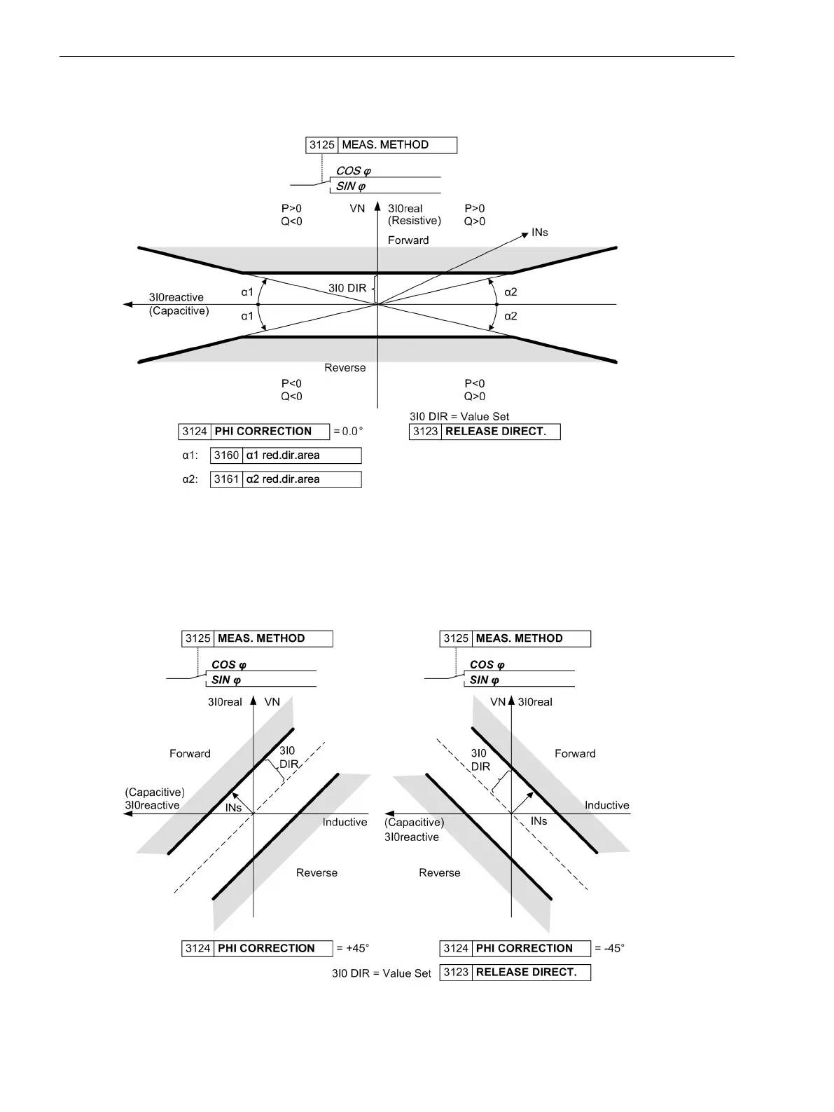
fore suitable for ground fault direction in resonant grounded systems where quantity 3Ι0 · cos ϕ is relevant.
The directional limit lines are perpendicular to axis 3Ι0
real
.
[7sj6-richtungskennlinie-bei-cos-messung-101210, 1, en_US]
Figure 2-82 Directional characteristic for cos–ϕ–measurement
The directional limit lines may be rotated by a correction angle (address PHI CORRECTION) up to ± 45°.
Therefore, in grounded systems it is possible e.g. to increase sensitivity in the resistive-inductive range with a
rotation of –45°, or in case of electric machines connected to the busbar of an ungrounded power system in
the resistive- capacitive range with a rotation of +45° (see the following Figure). Furthermore the directional
limit lines may be rotated by 90° to determine ground faults and their direction in isolated systems.
[richtungskennlinien-260602-kn, 1, en_US]
Figure 2-83 Directional characteristic for cos–ϕ–measurement
Functions
2.13 Ground Fault Protection 64, 67N(s), 50N(s), 51N(s)
202 SIPROTEC 4, 7SJ62/64, Manual
C53000-G1140-C207-8, Edition 08.2016

 Loading...


