Interlocked / Non-Interlocked Switching
The configurable command checks in the SIPROTEC 4 devices are also called "standard interlocking". These
checks can be activated via DIGSI (interlocked switching/tagging) or deactivated (non-interlocked).
Deactivated interlock switching means the configured interlocking conditions are not checked in the relay.
Interlocked switching means that all configured interlocking conditions are checked within the command
processing. If a condition is not fulfilled, the command will be rejected by a message with a minus added to it
(e.g. “CO–”), immediately followed by a message.
The following table shows the possible types of commands in a switching device and their corresponding
annunciations. For the device the messages designated with *) are displayed in the event logs, for DIGSI they
appear in spontaneous messages.
Type of Command Command Cause Message
Control issued Switching CO CO +/–
Manual tagging (positive / negative) Manual tagging MT MT+/–
Information state command, input blocking Input blocking ST ST+/– *)
Information state command, output blocking Output blocking ST ST+/– *)
Cancel command Cancel CA CA+/–
The "plus" appearing in the message is a confirmation of the command execution. The command execution
was as expected, in other words positive. The minus sign means a negative confirmation, the command was
rejected. Possible command feedbacks and their causes are dealt with in the SIPROTEC 4 System Description.
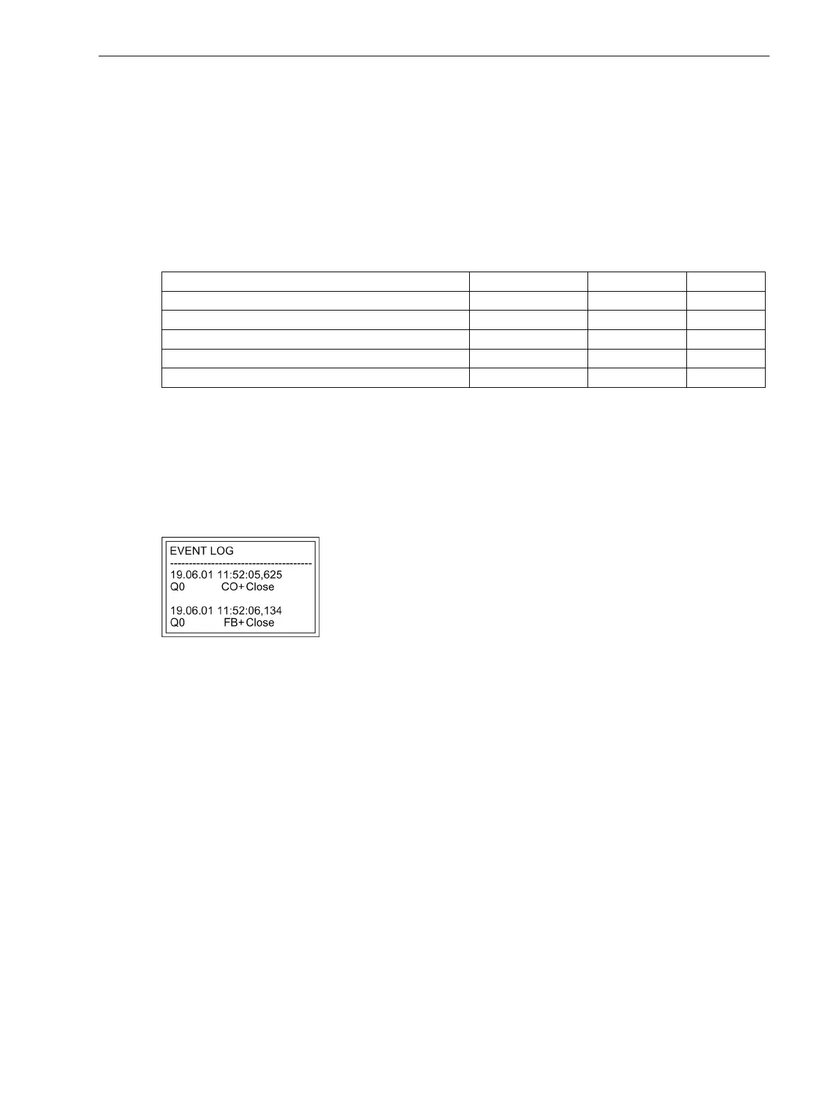
The following figure shows operational indications relating to command execution and operation response
information for successful switching of the circuit breaker.
The check of interlocking can be programmed separately for all switching devices and tags that were set with
a tagging command. Other internal commands such as manual entry or abort are not checked, i.e. carried out
independent of the interlocking.
[leistungsschalterbetriebsmeldung-020315-wlk, 1, en_US]
Figure 2-152 Example of an operational annunciation for switching circuit breaker 52 (Q0)
Standard Interlocking (default)
The standard interlockings contain the following fixed programmed tests for each switching device, which can
be individually enabled or disabled using parameters:
•
Device Status Check (set = actual): The switching command is rejected, and an error indication is
displayed if the circuit breaker is already in the set position. (If this check is enabled, then it works
whether interlocking, e.g. zone controlled, is activated or deactivated.) This condition is checked in both
interlocked and non-interlocked status modes.
•
System Interlocking: To check the power system interlocking, a local command is transmitted to the
central unit with Switching Authority = LOCAL. A switching device that is subject to system interlocking
cannot be switched by DIGSI.
•
Zone Controlled / Bay Interlocking: Logic links in the device which were created via CFC are interrogated
and considered during interlocked switching.
Functions
2.27 Breaker Control
SIPROTEC 4, 7SJ62/64, Manual 357
C53000-G1140-C207-8, Edition 08.2016

 Loading...


