Power Supply
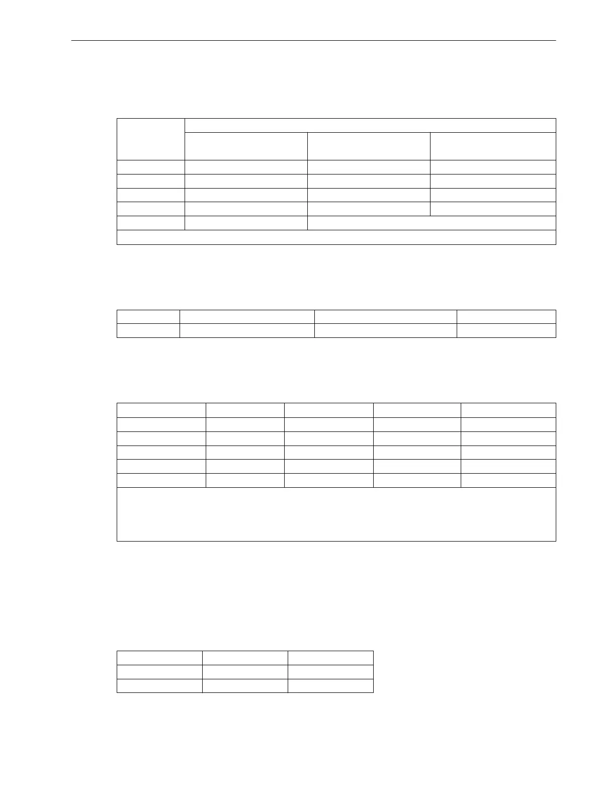
Table 3-12 Jumper setting of the nominal voltage of the integrated power supply on the processor board
C-CPU-2
Jumper Nominal voltage
DC 24 V to 48 V DC 60 V to 125 V DC 110 V to 250 V,
AC 115 V to 230 V
1)
X51 not used 1-2 2-3
X52 not used 1-2 und 3-4 2-3
X53 not used 1-2 2-3
X55 not used not used 1-2
not changeable interchangeable
1)
AC 230 V only possible for release 7SJ64**-.../CC and higher
Live Status Contact
Table 3-13 Jumper position of the quiescent state of the live status contact on the processor board C-
CPU-2
Jumper Open in the quiescent state Closed in the quiescent state Presetting
X40 1-2 2-3 2-3
Pickup Voltages of BI1 to BI5
Table 3-14
Jumper settings of the Pickup Voltages (DC voltage) of the binary inputs BI1 to BI5 on the
processor board C-CPU-2
Binary Input Jumper
DC 19 V Pickup
1)
DC 88 V Pickup
2)
DC 176 V Pickup
3)
BI1 X21 1-2 2-3 3-4
BI2 X22 1-2 2-3 3-4
BI3 X23 1-2 2-3 3-4
BI4 X24 1-2 2-3 3-4
BI5 X25 1-2 2-3 3-4
1)
Factory settings for devices with power supply voltages of DC 24 V to 125 V
2)
Factory settings for devices with power supply voltages of DC 110 V to 220 V and AC 115 V or 115 V to 230
V
3)
Use only with pickup voltages DC 220 V/ 250 V
RS232/RS485
The service interface (Port C) can be converted into an RS232 or RS485 interface by modifying the setting of
the appropriate jumpers.
Jumpers X105 to X110 must be set to the same position!
The presetting of the jumpers corresponds to the configuration ordered.
Table 3-15
Jumper settings of the integrated RS232/RS485 Interface on the processor board C–CPU-2
Jumper RS232 RS485
X103 and X104 1-2 1-2
X105 to X110 1-2 2-3
With interface RS232 jumper X111 is needed to activate CTS which enables the communication with the
modem.
Mounting and Commissioning
3.1 Mounting and Connections
SIPROTEC 4, 7SJ62/64, Manual 389
C53000-G1140-C207-8, Edition 08.2016

 Loading...


