•
Connect the ground on the rear plate of the device to the protective ground of the panel using at least
one M4 screw. The cross-sectional area of the ground wire must be equal to the cross-sectional area of
any other control conductor connected to the device. The cross-section of the ground wire must be at
least 2.5 mm
2
.
•
Connections are realized via the plug or screw terminals on the rear side of the device according to the
circuit diagram. When using forked lugs for screw terminals or in case of direct connections, the screws
must be screwed in so far that the screw heads align with the terminal block before inserting the lugs
and wires. A ring lug must be centered in the connection chamber in such a way that the screw thread
fits in the hole of the lug. The SIPROTEC System Description provides information regarding maximum
wire size, torque, bending radius and cable relief and must be observed.
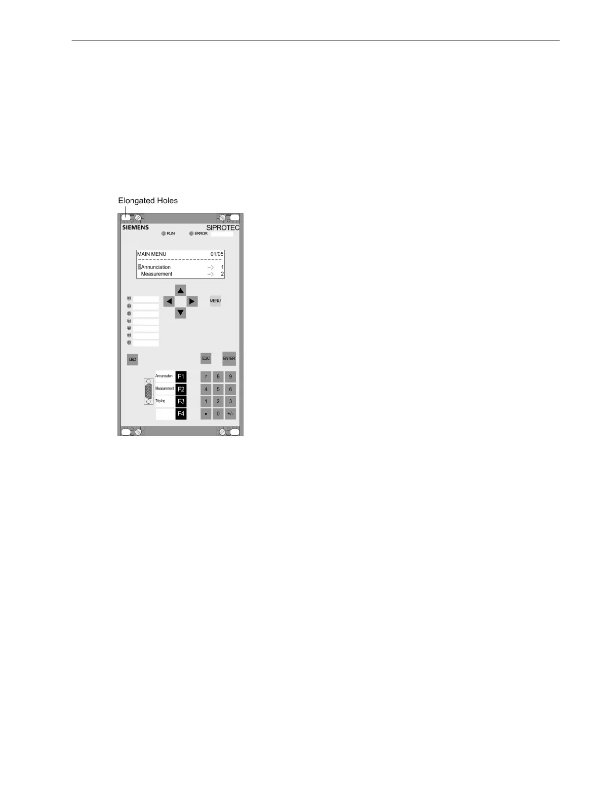
[schalttafeleinbau-gehaeuse-4zeilig-display-drittel-st-040403, 1, en_US]
Figure 3-26
Panel flush mounting of a device (housing size
1
/
3
)
Mounting and Commissioning
3.1 Mounting and Connections
SIPROTEC 4, 7SJ62/64, Manual 405
C53000-G1140-C207-8, Edition 08.2016

 Loading...


