[stromwdl-summenstromwdl-20070413, 1, en_US]
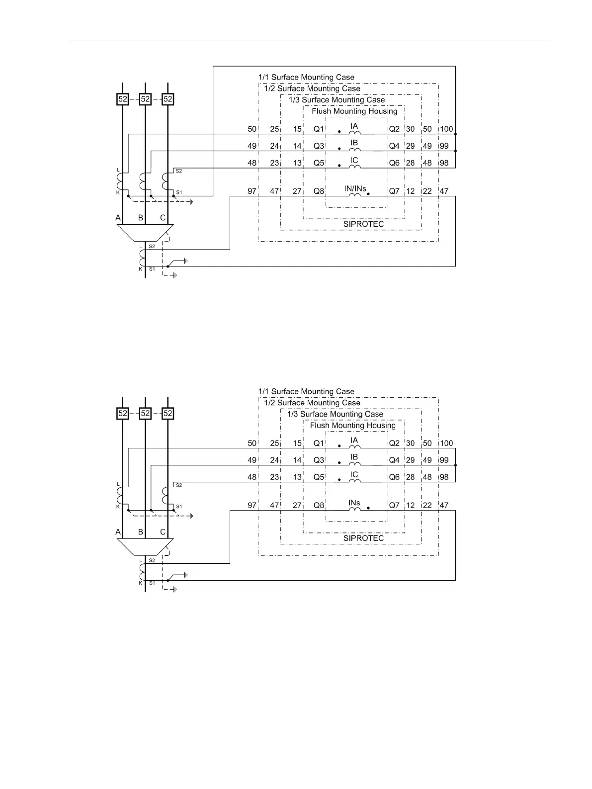
Figure C-3 Current connections to three current transformers, ground current from additional summation
CT, normal circuit layout
Important! Grounding of the cable shield must be effected at the cable's side
For busbar-side grounding of the current transformer, the current polarity of the device is changed via
address 0201. This also reverses the polarity of current input IN/INs. When using a cable-type current trans-
former, the connection of k and l at Q8 and Q7 must be changed.
[stromwdl-kabelumbauwdl-20070413, 1, en_US]
Figure C-4 Current connections to two current transformers, ground current of additional toroidal trans-
former for sensitive ground fault detection.
Important! Grounding of the cable shield must be effected at the cable's side
For busbar-side grounding of the current transformer, the current polarity of the device is changed via
address 0201. This also reverses the polarity of current input IN/INs. When using a cable-type current trans-
former, the connection of k and l at Q8 and Q7 must be changed.
Connection Examples
C.1 Connection Examples for Current Transformers, all Devices
SIPROTEC 4, 7SJ62/64, Manual 581
C53000-G1140-C207-8, Edition 08.2016

 Loading...


