²
Repeat the process for all other measuring points to be connected
As soon as the measuring points are correctly routed, the red markers are hidden. If not, perform a
consistency check.
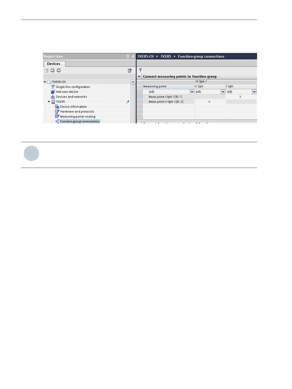
[scfgverb-310812-01.tif, 1, en_US]
Figure 7-10 Connecting Function Groups
NOTE
You can route the current measuring points using X (transformer neutral point in the direction of the
object) or using I (transformer neutral point in the opposite direction).
Adjusting Parameters
In order to adjust the parameters, proceed as follows:
²
Double-click in DIGSI 5 on Function Settings.
You will see the names of all available function groups.
²
Open the function group that contains the required function.
You will see the names of all the functions that this function group contains.
²
Double-click the name of the required function.
The parameter view will open in the operating range. This shows the parameters and the preset values of
the selected function.
Fault Recorder
7.1 Introduction to DIGSI 5
222 SIPROTEC 5, Fault Recorder, Manual
C53000-G5040-C018-5, Edition 11.2017

 Loading...


